Hello All,
I need to tie up an existing control system and send some alarms on a phone app when some errors occur. The existing system is placed into a metal enclosure that has some led lights from Eaton on the door with all the errors needed. All I want to do is to get the electrical signal from the door put it in Arduino with IoT capabilities and notify through Push notifications or email once an error occurs and subsequently a led is lit up.
Given the fact that this is an industrial application, I have chosen Arduino Opta. I have bought a SIM with Internet and connected the Opta to Arduino IoT, subscribed to the plan that allows triggers, and created a dashboard.
However, now I shall implement the physical part and I have some doubts as follows:
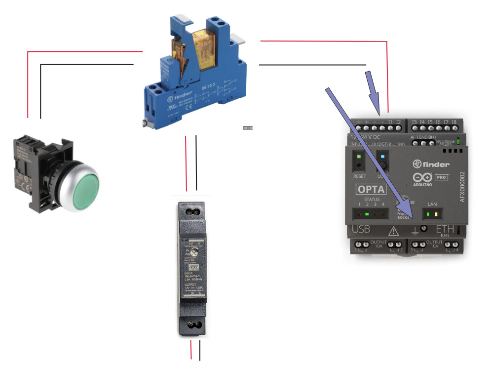
- To segregate the electrical circuits I will place a relay from Finder in between the LED and Arduino opta. The Relay will be powered up from an external source. I need just a digital input signal that shall tell me when the LED is HIGH. I have found some discrepancies in various datasheets from Arduino OPTA and I see in the PDF datasheet that the DI signal is at least 6.6 Volts as specified here in the VHL, and the DI voltage is 0 - 24 V DC capable.
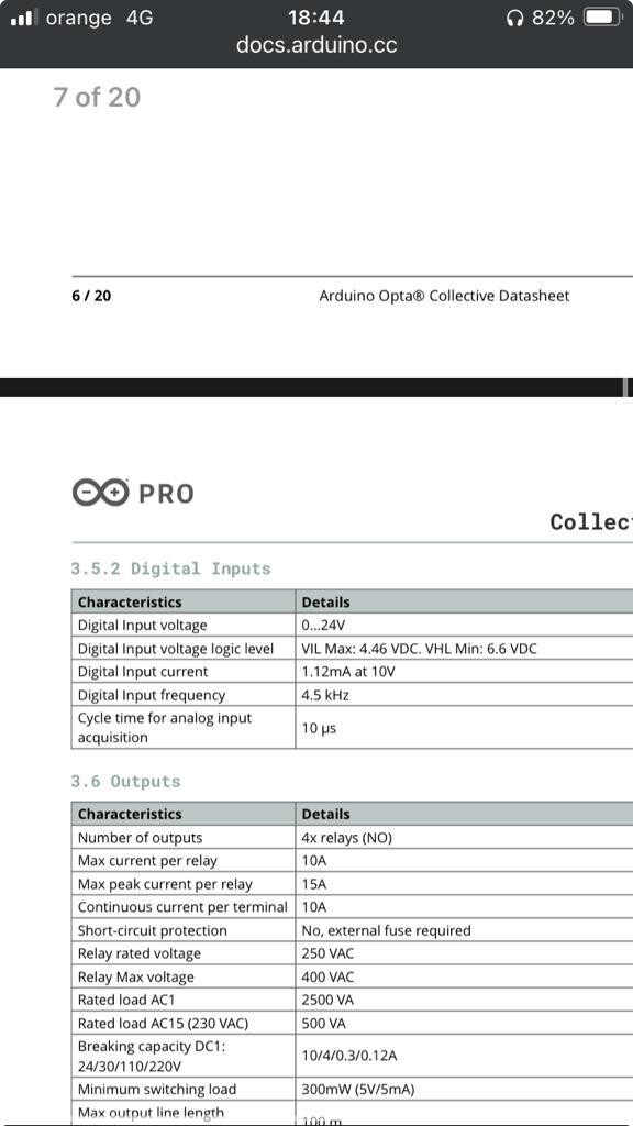
Then if I look at the pinout it seems the DI is 0 - 10V which contradicts the datasheet. Both pieces of information are from the official website:
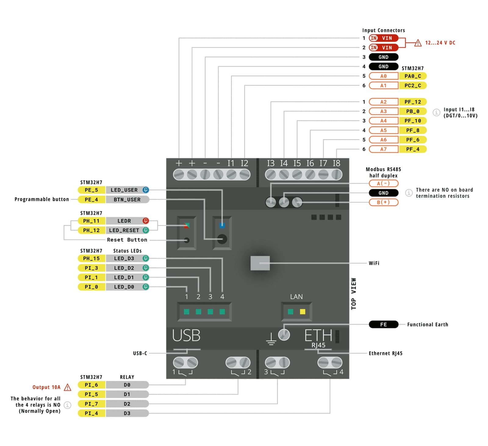
Anybody who tried a similar situation and can provide some feedback? I have 3 power supplies available: 5V, 12V and 24V. If 5V is not enough to trigger a high voltage and 12V is too much then I am in trouble.
- I will take the signal from the external power source, and the + of DC will be terminated into the respective INPUT from Arduino Opta. What about the - ? There is not a COM, I would normally terminate it into the GND, but is this ok in case I will use a different power supply from the one that powers up the Arduino Opta? It has 24V so it may not be used. I have created a small architecture sample - the arrows are my logic so far, one of them of course.
Thank you in advance,
M