Arduino - Photo Interrupter & Stepper Motor Project

Hi, I am a fairly new user to using the Arduino and have a small project, seeking some guidance on how best to implement it.

Project Materials

1 x Arduino Uno R3

1 x Arduino Motor Shield Rev3

1 x Haydon Kerk 15mm Stepper Motor (Bipolar, 5V)

1 x Push Button Switch

2 x Omron EE-SX972 (NPN) Photo Interrupter

Method (Idea how to implement)

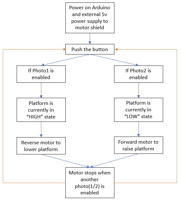
Arduino drives the stepper motor (which moves a platform up and down) and receives position input of the stepper motor via the photo interrupters, basic diagram as below:

image

The idea is that as the platform moves up or down, one of the photo interrupters gets triggered and then this stops the motor. In the above diagram, the platform is in the “HIGH” position and so when the push button is activated, it will sense that photo 1 is activated and photo 2 in not, so the motor direction will be to drive the platform to “LOW”. Once it moves down low enough, photo 2 will be activated and photo 1 will not be activated, so it will stop driving the stepper motor. When the button is activated again, it will move to the “HIGH” position.

How would it be best to code this, I have tried to use an “if” statement to run the modules (but looks like I'll have "if" statements within other "if" statement, which I guess is not ideal.) but was wondering if it would be better to use a “case” statement or some better was to implement? I’m new to using the Arduino so would be grateful for some ideas!

Here is the start of my code:

int delayLength = 30;
int led = 3;
int buttonPin = 5;
int photo1 = 4;
int photo2 = 6;

int valButton;
int valPhoto1;
int valPhoto2;

void setup() {
  
  pinMode(12, OUTPUT);
  pinMode(13, OUTPUT);
  
  pinMode(9, OUTPUT);
  pinMode(8, OUTPUT);

  pinMode(led, OUTPUT);
  pinMode(buttonPin, INPUT);

}

void loop(){
 
  val = digitalRead(buttonPin);

  if(valButton == HIGH){

    digitalWrite(led, HIGH);

    digitalWrite(9, LOW);  //ENABLE CH A
    digitalWrite(8, HIGH); //DISABLE CH B

    digitalWrite(12, HIGH);   //Direction CH A
    analogWrite(3, 255);   //Moves CH A
  
    delay(delayLength);
      
    digitalWrite(9, HIGH);  //DISABLE CH A
    digitalWrite(8, LOW); //ENABLE CH B

    digitalWrite(13, LOW);   //Direction CH B
    analogWrite(11, 255);   //Moves CH B
      
    delay(delayLength);
      
    digitalWrite(9, LOW);  //ENABLE CH A
    digitalWrite(8, HIGH); //DISABLE CH B

    digitalWrite(12, LOW);   //Direction CH A
    analogWrite(3, 255);   //Moves CH A
      
    delay(delayLength);
        
    digitalWrite(9, HIGH);  //DISABLE CH A
    digitalWrite(8, LOW); //ENABLE CH B

    digitalWrite(13, HIGH);   //Direction CH B
    analogWrite(11, 255);   //Moves CH B
      
    delay(delayLength);
}
    
  else{
    
    digitalWrite(led, LOW);

  }

}

How is the button wired? Any pull down resistor used?
When the button is detected full speed is ordered on channel A. Then the execution makes a stop for 30 mS. Then channel B gets full power.... It looks wierd to me.
Please show a flow chart showing how the code is intended to work.

The combination of the motor shield and the stepper motor will not work well.

The Arduino Motor Shield Rev3: Arduino Motor Shield Rev3 — Arduino Official Store
It has a L298, which is intended for small 12V DC motors. The L298 has a voltage drop of 2.5 to 3V and is therefor almost useless for 5V motors. It is also not suited for stepper motors.

Is this your stepper motor: 15mm Can-Stack Stepper Motor Linear Actuator
Does it look the same ? there seems to be other versions.
Most stepper motors are current controlled. I see that your stepper motor has indeed a rating of 5V.
Everyone seems to use a A4988 module for stepper motors, so that might be a good choice.

How do you power your project ? The 5V pin of the Arduino Uno is not a power output for motors.

It took me a while to check if the Omron EE-SX972 will work at 5V. The page for the EE-series has a document, and in that document, look for the "EE-SX97" series. It will work at 5V.

1 Like

Check out the State Change Detection example in the IDE (File->examples->02.digital->State Change Detection) to learn how to detect when your button is pressed, not if your button is pressed.

Rather than a bunch of nested if() statements or switch/case statements, a simple state machine would be easier to implement.

When the button is pressed, your code checks both your sensors to determine if you need to move UP or DOWN. This is your new state. Each time through loop(), you read both sensors and then, depending on your state, you look for one of them to be tripped (done moving) or not (keep moving).

2 Likes

I was thinking of just wiring the button directly to one of the digital input pins and a 10k pull down resistor - The flow would be:

So in the code, that was just playing around but instead of the delay I was thinking that I would put in a statement that would wait for either photo1 or photo2 being activated and then it would stop.

Oh I did not see that, I was under the impression with the L298 that it's operating voltage was 5-12V which would translate across to working with the motor, I will look into a backup option.

That is the correct motor model, I will be using the 5v version and was going to use a 5v external power supply to the motor shield.

Ah, that's really useful to know! Definitely will be a good start.

So basically, it will poll the button state and do nothing until it is pressed.

if button state is "HIGH"
** if photo1 is enabled (then platform is "HIGH")**
** drive platform down**

My question here is how would I handle the motor driving down UNTIL it enables photo2?
Would it be okay to code in a "do while" loop? ie.

if button state is "HIGH"
** if photo1 is enabled (then platform is "HIGH")**
** do motor driving platform down**
** while photo2 is disabled**

else if photo2 is enabled (then platform is "LOW")
** do motor driving platform up**
** while photo1 is disabled**

Would this be okay way to code it or is there a better way to go about it?

That works but You can use the built in feature of INPUT_PULLUP instead of just INPUT. Reverse the logic by a "!" close to the digital read.

Your flowchart is good but that's not the way the code is made.
You've got some suggestions already so I don't add any new ones.

1 Like

The A4988 starts working at 8V for the motors :frowning_face:
The DRV8833 is better :smiley: it is intended for low voltage stepper motors. It will work with the Arduino Stepper library.

The directions by blh64 in post #4 are spot on :white_check_mark: Can you make such a sketch ?
Actually, there is no other way, even if I think really hard :brain:

I have made a bad sketch without a plan, but with the directions of blh64. Shall I show it here ? or is this an assignment for school ?
afbeelding

1 Like

Thanks for the schematic, I have ordered the materials and went for the DRV8833 as it was in stock.
I had a go at the sketch, is this something how it should look?

#include <Stepper.h>

const int buttonPin = 2;
const int ledRaised = 3;
const int ledLowered = 4;

int photo1 = 6;
int photo2 = 7;

int valButton;
int valPhoto1;
int valPhoto2;
int val1;
int val2;

int buttonPushCounter = 0;
int buttonState = 0;
int lastButtonState = 0;

Stepper stepper(4, 5, 6, 7);

void setup(){
  Serial.begin(9600);
  stepper.setSpeed(60);

  pinMode (buttonPin, INPUT); //Button State Detection
  pinMode (photo1, INPUT);  //Photo Interrupter 1
  pinMode (photo2, INPUT);  //Photo Interrupter 2

  pinMode (ledRaised, OUTPUT);  //LED That Turns On When Platform Raised
  pinMode (ledLowered, OUTPUT); //LED That Turns On When Platform Lowered
}

void loop(){
  Serial.println("Forward");
  stepper.step(STEPS);
  Serial.println("Backward");
  stepper.step(-STEPS);
}

void loop(){
  buttonState = digitalRead(buttonPin);
    if (buttonState == HIGH) {
      val1 = digitalRead (photo1); //Read Value Of Photo-Interrupter 1
      val2 = digitalRead (photo2); //Read Value Of Photo Interrupter 2
      if (val1 == HIGH){
        digitalWrite (ledRaised, HIGH); //Platform Is In The Raised Position
        do {
          stepper.step(-10) //Lower Platform
          val2 = digitalRead (photo2);
        } while (val2 == LOW);
        else if (val2 == HIGH){
          digitalWrite (ledLowered, HIGH);  //Platform Is In The Lowered Position
          do {
            stepper.step(10)  //Raise Platform
            val1 = digitalRead (photo1);
          } while (val1 == HIGH)
          }
        }
      }
    } else {
      //Do Nothing
    }
    delay(50);
  }

It is always better to name your variables for what they do, such as photoHigh, photoLow vs. photo1 and photo2. Something like this should get your close...

#include <Stepper.h>

const int buttonPin = 2;
const int ledRaised = 3;
const int ledLowered = 4;

const int photoHighPin = 6;  // was photo1
const int photoLowPin = 7;   // was photo2

int valHigh;
int valLow;

int buttonState = 0;
int lastButtonState = 0;

const int stepsPerRevolution = 200;  // change this to fit the number of steps per revolution
Stepper stepper(stepsPerRevolution, 4, 5, 6, 7);

enum { HIGH_STATE, LOW_STATE, MOVING_UP, MOVING_DOWN };
int currentState;

void setup() {
  Serial.begin(9600);
  stepper.setSpeed(60);

  pinMode (buttonPin, INPUT); //Button State Detection
  pinMode (photoHighPin, INPUT);  //Photo Interrupter 1
  pinMode (photoLowPin, INPUT);  //Photo Interrupter 2

  pinMode (ledRaised, OUTPUT);  //LED That Turns On When Platform Raised
  pinMode (ledLowered, OUTPUT); //LED That Turns On When Platform Lowered

  findInitialState();  // determine where we are when powered up
}


void loop() {
  readSensors();  // update photo sensors

  switch ( currentState ) {
    case HIGH_STATE:
      // idle at high location, nothing more to do
      break;

    case LOW_STATE:
      // idle at low location, nothing more to do
      break;

    case MOVING_UP:
      // actively moving up so check if upper photo sensor has tripped
      // if yes, stop, if not, take another step
      if ( valHigh ) {
        // we have reached our goal
        currentState = HIGH_STATE;
      } else {
        // still moving
        stepper.step(1);
      }
      break;

    case MOVING_DOWN:
      // actively moving downp so check if lower photo sensor has tripped
      // if yes, stop, if not, take another step
      if ( valLow ) {
        // we have reached our goal
        currentState = LOW_STATE;
      } else {
        // still moving
        stepper.step(-1);
      }
      break;
  }

  buttonState = digitalRead(buttonPin);
  if (buttonState != lastButtonState) {
    if (buttonState == HIGH) {
      Serial.println("Button pressed");
      switch (currentState) {
        case HIGH_STATE:
        case MOVING_UP:
          // we are either at the top or moving up, so reverse
          currentState = MOVING_DOWN;
          Serial.println("Moving Down");
          break;

        case LOW_STATE:
        case MOVING_DOWN:
          // we are either at the bottom or moving down, so reverse
          currentState = MOVING_UP;
          Serial.println("Moving Up");
          break;
      }
      delay(20); // debounce
    }
  }
  lastButtonState = buttonState;
}


void readSensors() {
  // read both photo sensors and set LEDs accordingly
  valHigh = digitalRead(photoHighPin);
  valLow = digitalRead(photoLowPin);

  digitalWrite(ledRaised, valHigh);
  digitalWrite(ledLowered, valLow);
}


void findInitialState() {
  // determine inital state at power-up
  readSensors();
  if ( valHigh && !valLow ) {
    // at HIGH
    currentState = HIGH_STATE;
  } else if ( !valHigh && valLow ) {
    // at LOW
    currentState = LOW_STATE;
  } else if ( !valHigh && !valLow ) {
    // not at either end of travel so start moving down
    currentState = MOVING_DOWN;
  } else {
    // both sensors are tripped so something is wrong
    Serial.print("Both sensors are tripped. Check the wiring. Something is wrong");
    while (1); // loop forever
  }
}
1 Like

Here is the sketch that I made yesterday:

// For: 
//   https://forum.arduino.cc/t/arduino-photo-interrupter-stepper-motor-project/1040942
//
// Using the "StepperOneStepAtATime" from:
//   https://docs.arduino.cc/learn/electronics/stepper-motor
//
//
// Something bad happened here. I started coding and coding and coding, 
// but in the end there was no real plan for the structure or a full safety check.
// That's just wrong. This is a beginners sketch.
//

#include <Stepper.h>

const int stepsPerRevolution = 200;  // depends on the stepper motor

Stepper myStepper(stepsPerRevolution, 11, 12, 10, 9);

const int ledPin = 3;         // A PWM pin for the LED
const int buttonPin = 5;      // HIGH if pressed
const int photoUpperPin = 6;  // Upper photointerrupter, active LOW
const int photoLowerPin = 4;  // Lower photointerrupter, active LOW

int state;                    // +1 is up, -1 is down, 0 is not moving
int count;                    // counts the number of steps

int lastButtonState;          // for the State Change Detection for the button

const int safetyDistancePhoto = 200;  // steps to be sure that photointerruptor is released

void setup() 
{
  Serial.begin(115200);
  Serial.println( F("Hello, the sketch is running."));
  Serial.println( F("Slide the switches to the left to for the upper and lower signals."));

  pinMode(ledPin, OUTPUT);
  pinMode(buttonPin, INPUT);
  pinMode(photoUpperPin, INPUT_PULLUP);
  pinMode(photoLowerPin, INPUT_PULLUP);

  myStepper.setSpeed(20);     // This also works with single steps

  // Initialize variables.
  // Normally, the stepper motor should go to the default position if it is in the middel.
  // Check if it is already in a position.
  state = 0;                  // default, not moving
  count = 0;
  lastButtonState = LOW;      // active HIGH, assuming button is not pressed.

  // Blink the led, just for fun.
  for( int i=0; i<5; i++)
  {
    digitalWrite( ledPin, HIGH);
    delay( 200);
    digitalWrite( ledPin, LOW);
    delay( 200);
  }

  Serial.println( F("Press the button to move up."));
}

void loop()
{
  if( state == 0)                                  // not moving ?
  {
    // The stepper motor is not moving.
    // The position should be in the upper or lower position.
    // Check if the button is pressed.

    int buttonState = digitalRead( buttonPin);     // debouncing later on with delay
    if( buttonState == HIGH and lastButtonState == LOW)  // button was just pressed ?
    {
      // Check the photointerruptors to see where it is
      int photoUp = digitalRead( photoUpperPin);   // upper photointerruptor
      int photoDown = digitalRead( photoLowerPin); // lower photointerruptor

      if( photoUp == LOW and photoDown == HIGH)    // in highest position ?
      {
        state = -1;                                // going down
        count = 0;                                 // count the steps
        Serial.println( F("Going down..."));
      }
      else if( photoUp == HIGH and photoDown == LOW)  // in lowest position ?
      {
        state = +1;                                // going up
        count = 0;                                 // count the steps
        Serial.println( F("Going up..."));
      }
      else if( photoUp == LOW and photoDown == LOW)
      {
        Serial.println( F("Error, both photointerruptors are active."));
        Serial.println( F("Not moving for safety."));
      }
      else if( photoUp == HIGH and photoDown == HIGH)
      {
        Serial.println( F("Error, position unknown."));
        Serial.println( F("No photointerruptor is active."));
        Serial.println( F("Not moving for safety."));
      }
    }
    lastButtonState = buttonState;
    delay( 20);                                    // an ugly way to debounce the button
  }
  else
  {
    // The stepper is moving, check the photointerruptors after each step.
    myStepper.step( state);                        // make one step
    count++;                                       // increment number of steps

    int photoUp = digitalRead( photoUpperPin);     // upper photointerruptor
    int photoDown = digitalRead( photoLowerPin);   // lower photointerruptor
    
    if( state == +1 and photoUp == LOW)            // reached the upper limit ?
    {
      state = 0;                                   // stop the stepper
      Serial.print( F("Reached Upper after "));
      Serial.print( count);
      Serial.println( F(" steps."));
      Serial.println( F("Press the button to move down."));
    }
    else if( state == -1 and photoDown == LOW)    // reached the lower limit ?
    {
      state = 0;
      Serial.print( F("Reached Lower after "));
      Serial.print( count);
      Serial.println( F(" steps."));
      Serial.println( F("Press the button to move up."));
    }
    else if( state == +1 and photoDown == LOW and count > safetyDistancePhoto)
    {
      Serial.println( F("Error, lower switch did not release while going up."));
      Serial.println( F("Stopped for safety."));
      state = 0;
    }
    else if( state == -1 and photoUp == LOW and count > safetyDistancePhoto)
    {
      Serial.println( F("Error, upper switch did not release while going down."));
      Serial.println( F("Stopped for safety."));
      state = 0;
    }
    else if( photoUp == LOW and photoDown == LOW)
    {
      Serial.println( F("Error, both photointerruptors activated."));
      Serial.println( F("Stopped for safety."));
      state = 0;
   }
  }
}

The sketch in Wokwi simulation:

Start the simulation. The sliding switches are the photointerrruptors. Click on them to change the position. To the left is active. Have fun :partying_face:
Wokwi does not have a DRV8833, so I connected the stepper motor to the Arduino Uno (the Wokwi simulation has unlimited power), but that is not possible in real life.

@jeromeplaud Both blh64 and me use the Stepper library to make 1 step each time. That is needed to check the photointerruptors. We both use the State Change Detection. We both read both photointerruptors and then decide what to do. We do not use a while-statement.

Try to use our code as an example and make your own sketch.

@blh64 in C++, the 'enum' is no longer a define, but it is a type. The type is a constant value of the 'enum' type.
You can do this:

enum currentState { HIGH_STATE, LOW_STATE, MOVING_UP, MOVING_DOWN };

or simplify the variable name with:

enum state {HIGH_STATE, LOW_STATE, MOVING_UP, MOVING_DOWN};

The 'currentState' or 'state' is no longer a integer, but it is the type 'enum'.

1 Like

@blh64 % @Koepel

Thanks so much for the sketches guys, much appreciated!

I did not know about the simulation software, will definitely give it a go while I wait for my hardware to arrive. Woo!

This topic was automatically closed 180 days after the last reply. New replies are no longer allowed.