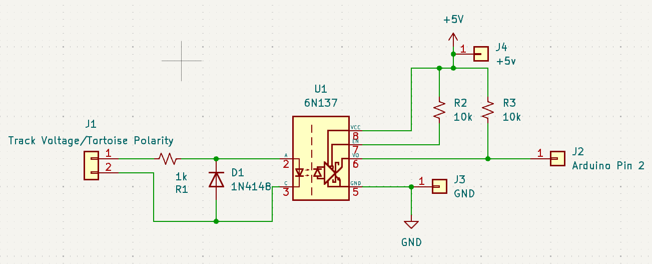
I'm building a project that uses an Arduino to detect the polarity of a 12 volt DC switch. I tried using an optocoupler with the suggested circuitry for that voltage, and can't see any problems with it, however the optocoupler keeps burning out.
Is an optocoupler the best way to do this, or how would you guys do this? If you think that an optocoupler is the best way to go, I'll post some photos of the schematics. Maybe I missed something.
Hi, @outbackhut
Have you used a current limit resistor in series with the input to the opto-coupler?
Can you please post a copy of your circuit, a picture of a hand drawn circuit in jpg, png?
Hand drawn and photographed is perfectly acceptable.
Please include ALL hardware, power supplies, component names and pin labels.
"Polarity" do you mean if the switch is ON or OFF, or the polarity of the voltage it is switching?
Thanks.. Tom.. 


I'm detecting the voltage polarity of a model railway tortoise. If the points are against me, I'm using a relay to shut down a small section of track in front of the points so that the locomotive doesn't derail.
I have a current limiting resistor and a diode.
I know that schematic is a bit messy, but it's readable, and that's ultimately what matters.
I use a 6N137 in a not dissimilar situation (DCC signal detection for a turnout decoder, 15V level signal) and use a 4.7K resistor for R1. No problems in over a year of operation. I do use a red LED in place of your D1 signal diode.
I suppose the point of the red LED would be that it is a visual way of knowing that that resistor is good enough. Maybe I'll try replacing R1 with 4.7k resistor
D1 is a small signal diode, so that will melt rather than give any protection. Use a 1N4001 as your protection diode.
I have a bunch of 1N4004. Will that work, or should I go get some 1N4001?
Yes it will be fine, the last number just gives the reverse breakdown figure. A 1N1004 just has a bigger breakdown voltage which is a good thing, but you are not going to get anywhere even close to it with either diode.
My bad, I actually only have 1N4007
The point of using a diode/LED reverse biased to the optocoupler's LED is to not exceed the maximum reverse voltage on the optocoupler's LED (5V). I used a LED both as a signal indicator and to more or less balance the input current for both polarities (since the external LED has a forward voltage drop closer to that of the optocoupler's LED than a regular diode would). With a 4.7K resistor and a 12V input you won't come close to hitting the forward current limit on either an LED or a signal diode.
Well, that worked.
Only issue now is that the arduino keeps reading the polarity incorrectly, which it didn't with the other diode/resistor (when it worked and didn't go pop)
It sometimes reads the polarity as - +, not + -. If that makes sense.
I don't see how the 1N4148 will melt when used with such a high limiting resistor. Even if the input voltage is 12V the current will be limited to 12 ma.
That being said, if I place my finger on a ground pin, it reads correctly, every time.
Sometimes? If it did it all the time, I'd ask if you remembered that the output of the 6N137 is low rather than high when its internal LED is on. But sometimes... the only thing that comes to mind would be to reduce R1 to 3.9K and see if 4.7K was just a little too much current limited for 12V vs 15V.
And I just realized that your schematic fragment isn't showing a 0.1uF bypass cap between pins 5 and 8. That feels more like it could be the problem.
Hmmm, yes. I missed that off the datasheet...
Right, let's try that!
Can you define why you think the opto is burning out? Looking at your schematic it appears to be right. I can see nothing that would burn the opto out.
Well, I had two optocouplers completely stop working. Pulled them out of their socket on my circuit board, and tested them in a different circuit/breadboard, and power was coming out of pins it shouldn't have, and it was getting insanely hot at very low voltages.
That screams of burnt out to me.
I wondered if perhaps the 1N4148 was attached backwards (i.e. anode to anode/cathode to cathode with the O/C) and allowing the maximum reverse voltage (5V) on the 6N137's LED to be exceeded.