A new version is available!
Download here: http://pighixxx.com/prominiv3_0.pdf
A new Pinout is available:
ARDUINO PRO MINI
Versione 1.1
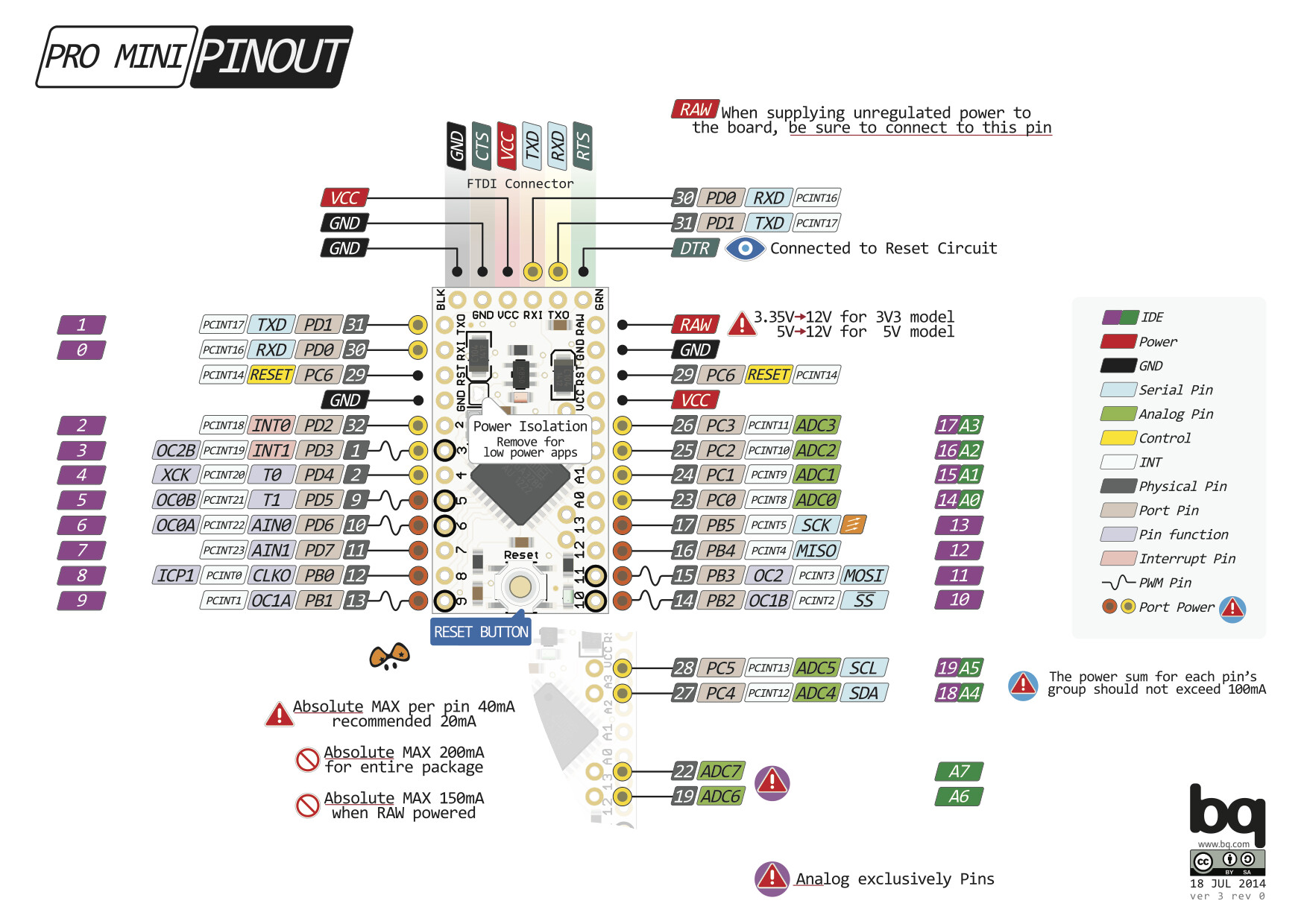
Arduino Pro MiniATMEGA168 PINOUT
ATMega168.Bye,
PighiXXX
A new version is available!
Download here: http://pighixxx.com/prominiv3_0.pdf
A new Pinout is available:
ARDUINO PRO MINI
Versione 1.1
Arduino Pro MiniATMEGA168 PINOUT
ATMega168.Bye,
PighiXXX
ATMega168 processor pinout added.
New version (1.1) on line.
Hi
Can I flag an error.
At the top left of the diagram there are two pins with the SCL label. The upper one should be labeled SDA.
Otherwise a great diagram.
Arduino Pro mini haven't pin 19 and 22 (ADC6 and ADC7) Why ?
Knight_FlyCn:
Arduino Pro mini haven't pin 19 and 22 (ADC6 and ADC7) Why ?
Not part of the original design, basically because the DIP chip used in the UNO does not bring them out.
Later versions (clones) of the Pro Mini however, have added them.
The pinout links are unfortunately down... ![]()
A new version is available!
Download here: http://pighixxx.com/prominiv3_0.pdf
Thankyou! This is far easier to read this than the silkscreen on these clone boards
Geoff
Thanks!
Meanwhile same download new version (3.1)
Noob question here, but is this the same pinout for the Pro Mini 5v 16mhz atmega328?
Yes,
but it depends on the version, maybe they can miss some analog pins
Very nice graphic. There may be a problem, however. According to this:
arduino.cc/en/uploads/Main/Arduino-Pro-Mini-schematic.pdf
the pins for MOSI and MISO are swapped. This is referring to the pdf, v3r1, BTW. The png of v3r0 seems correct.
Isaac
isaacw:
Very nice graphic. There may be a problem, however. According to this:arduino.cc/en/uploads/Main/Arduino-Pro-Mini-schematic.pdf
the pins for MOSI and MISO are swapped. This is referring to the pdf, v3r1, BTW. The png of v3r0 seems correct.
This just caught me out - it does seem like v3.1 has MOSI and MISO switched from how they actually are on the board I'm using. They were correct in v3.0.
/dan
May I ask what software you use to create your pinouts? I enjoy referring to them as they are clear and easy to use.
Thanks.
Nice job if you are the designer. But there are some mistakes. A4-A7 pins below the board must be shifted little bit upper (red rings), because they are not in the same raster as other pins. On the board it is correct. Then pin description is connected to the main pin, not to A4-A7.
Pity about the MISO / MOSI screw-up. I'll bet that's caught a lot of people out by now.
V3.1 should be scrapped, and completely removed from this thread, or pighixxx should at least edit and make it clear that there's an error, rather than just leaving it as he's done.
What do the red and black rings around some of the pads mean?
The red (or rather pink) rings are marking the A4, A5, and the bonus A6 and A7 that come with the TQFP version of the Atmel chip.
Because they are on a bit of an odd place, they are marked, and explained below.
By the way, the remarks made by vprheli are either corrected, or incorrect.
The pins are shown as they are, with an offset to the other pins.
But you have to take a real good look to see that.
And to be honest i don't think it's that important to have them drawn at the exact correct spot for the purpose of this drawing.
I can't tell you anything about those black rings.