Alright, bear with me...
As we all know, internal arduino pwm can be modified. After searching, I finally understand the code:
void setup()
{
 // configure hardware timer2 to generate a fast PWM on OC2B (Arduino digital pin 3)
 // set pin high on overflow, clear on compare match with OCR2B
 TCCR2A = 0x23;
 TCCR2B = 0x0C;  // select timer2 clock as 16 MHz I/O clock / 64 = 250 kHz
 OCR2A = 249;  // top/overflow value is 249 => produces a 1000 Hz PWM
 pinMode(3, OUTPUT);  // enable the PWM output (you now have a PWM signal on digital pin 3)
 OCR2B = 125;  // set the PWM to 50% duty cycle
}
from Controlling 4-pin computer fans - PWM at 25khz? - Interfacing - Arduino Forum
I implemented it in this:
/*
Eddy's temperature sensor and PWM fan speed controller.
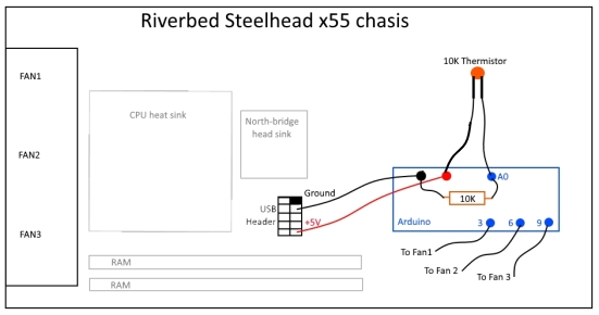
This project was made to be placed inside the Riverbed x55 chasis.
See: https://makeitbreakitfixit.com/2016/06/20/hacking-a-riverbed-steelhead-cx755/
This code is protected under the GNU GENERAL PUBLIC LICENSE.
See https://github.com/Aristocles/TempController for more info.
www.makeitbreakitfixit.com
June 2016
This program reads the input from a thermistor (temperature sensor) and provides a PWM
signal to 3 fans to either switch them off or spin them at various speeds accordingly.
*/
//Modified in May 2019 by foxxyman: https://id.arduino.cc/foxxyman. Original info above^^
//The Original copy is under the GNU General Public License, and as such I convey the same GNU General Public License terms in this copy.
//Anyone having a problem with the above, please contact foxxyman: https://id.arduino.cc/foxxyman.
unsigned int serial_baud = 9600; // Serial baud speed. Must match the baud set in Linux script file
// There are three temperature thresholds with corresponding fan speeds. All temps in celsius.
// You can configure the temperature variables below, but the explanation below uses the default values.
// Between 0 and 34 degrees the fan is off.
// Once temp reaches 35 degrees, LOW_FAN speed begins
// If temp drops below 30, the fan switches off again. If the temp rises above 45 MID1_FAN speed begins
// If temp drops below , the fan drops back to LOW_FAN speed. If the temp rises above 55 MID2_FAN speed begins
//If the temp rises above 65 HI_FAN speed begins
// If temp drops below , the fan drops back to MID_FAN speed.
int low_min_temp = 35;
int low_max_temp = 45;
int mid1_min_temp = 45;
int mid1_max_temp = 55;
int mid2_min_temp = 55;
int mid2_max_temp = 65;
int hi_min_temp = 65;
int hi_max_temp = 100;
int warning_temp = 85; // temp that the warning led turns on at
// Fan power is a PWM signal between 0 and 255.
int slo_fan_speed = 60;
int mid1_fan_speed = 120;
int mid2_fan_speed = 185;
int max_fan_speed = 255;
//
int dly = 1000; // Delay in ms to wait between polling temp sensor
bool testing = false; // Setting to true sends cycling false temperatures. For testing only.
int fanSpeed = 0;
int temp = 1;
bool incrementing = true;
#define THERMISTOR A0 // Analog pin for temp sensor
#define FAN1 3 // All 3 fans are controlled the same
#define FAN2 6 //
#define FAN3 9
#define LED 1 // the warning led
void setup() {
Serial.begin(serial_baud); // Serial sync speed
pinMode(FAN1, OUTPUT); // PWM output pins
pinMode(FAN2, OUTPUT);
pinMode(FAN3, OUTPUT);
delay(500);
pinMode(LED, OUTPUT);
// configure hardware timer2 to generate a fast PWM on OC2B (Arduino digital pin 3)
// set pin high on overflow, clear on compare match with OCR2B
TCCR2A = 0x23;
TCCR2B = 0x09; // select timer2 clock as 16 MHz I/O clock / 64 = 250 kHz
OCR2A = 79; // top/overflow value is 249 => produces a 1000 Hz PWM
pinMode(3, OUTPUT); // enable the PWM output (you now have a PWM signal on digital pin 3)
OCR2B = 125; // set the PWM to 50% duty cycle
}
void loop() {
double temp = Thermister(analogRead(THERMISTOR)); // Read temp sensor
fanSpeed = actionCheck(temp, fanSpeed); // Checks temp and returns one of 4 actions for fans:
Serial.print("["); Serial.print(temp); Serial.print("deg] "); //0 = off, 1 = slow, 2 = mid, 3 = max
executeAction(fanSpeed); // Sets the fans to appropriate action
delay(dly);
if(temp > warning_temp) {
digitalWrite(LED, HIGH); //if the temp is higher than 85 degrees celsius,
} else { //than led turns on
digitalWrite(LED, LOW); //if not, it’s off
}
}
//
// FUNCTIONS:
//
double Thermister(int RawADC) {
if (testing) {
if (temp >= (hi_max_temp + 9)) incrementing = false;
if (temp <= 0) incrementing = true;
if (incrementing) temp++;
else temp--;
return (temp % (hi_max_temp + 10)); // executed during testing
}
double temp = log(((10240000/RawADC) - 10000));
// See http://en.wikipedia.org/wiki/Thermistor for explanation of formula
temp = 1 / (0.001129148 + (0.000234125 * temp) + (0.0000000876741 * temp * temp * temp));
temp = temp - 273.15; // Convert Kelvin to Celcius
return temp;
}
int actionCheck(int temp, int fanSpeed) {
switch (fanSpeed) {
case 1:
if (temp < low_min_temp) return 0;
case 2:
if (temp < mid1_min_temp) return 1;
case 3:
if (temp < mid2_min_temp) return 2;
case 4:
if (temp < hi_min_temp) return 3;
}
if (temp > hi_max_temp) return 4;
if ((temp > mid2_max_temp) && (fanSpeed == 1)) return 2; // the fanSpeed part ensures that the change only occurs when temp going up, not down
if ((temp > low_max_temp) && (fanSpeed == 0)) return 1;
return fanSpeed;
}
void executeAction(int fanSpeed) {
Serial.print("Fan speed set to: "); Serial.println(fanSpeed);
int rpm;
switch (fanSpeed) {
case 1:
rpm = slo_fan_speed;
break;
case 2:
rpm = mid1_fan_speed;
break;
case 3:
rpm = mid2_fan_speed;
break;
case 4:
rpm = max_fan_speed;
break;
default:
rpm = 0;
}
analogWrite(FAN1, rpm);
analogWrite(FAN2, rpm);
analogWrite(FAN3, rpm);
}
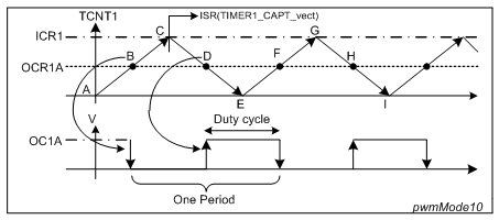
Obviously, I need the duty cycle to not be a constant. From what I understand, the duty cycle looks like it is constant in the code I have so far. Correct if I'm wrong. How do I make the duty cycle variable?
I have read: https://www.arduino.cc/en/Tutorial/SecretsOfArduinoPWM but if the explaination is in there, I don't understand it.
-Thank you