Arduino serial communication with Home Automation Device (RS-485)

Hi people of this forum! You are all very talented and I hope you could shed light on the following issue:

I have smart home automation equipment that I would like to control from an Arduino.
Take this 12 Channel Relay module as an example

It can get 12 loads connected to the 12 channels that it has.

This module can be controller with serial communication via a Protocol called Smart-BUS (proprietary documented protocol)
When connecting a Smart Panel that I have to the bus, the smart panel can be programmed via a special application to turn on/off specific channels. This smart panel is using the Smart-BUS protocol as well.
The company documented the protocol so it can be used by developers
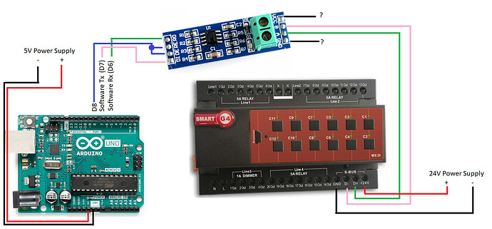
What I would like to do is to make an Arduino behaves like a Smart Panel and to be able to control the 12 channels module from the Arduino, something like this:


(Click here for enlarged image)

This is written in their website regarding the Smart-BUS protocol:

"Smart-BUS ®" is a patented Protocol (Patent No: 201110123081.0) Based on "Advanced RS485" 64 Bits Communication. This 2-Way Smart-BUS Communication Protocol was Designed Mainly for Home Automation Industry and thus many call it today "SmartHome-BUS" or Simply "S-BUS".
S-BUS Operating Voltage:
The S-BUS Engine can work at wide Voltage DC Range between 8-32Volts. And is considered Green as it consumes between 20-32mA per device during operation. The S-BUS uses 4 Wires (2-Pairs): one Pair for Data Communication and the other for Power. The Smart-BUS has Also Several Lines of protection like: Reverse Polarity Protection, Short Circuit protection, Overload Protection, Overheat protection, and other..

(Link to page is here: Smart-Bus (S-BUS) Technology : Home Automation)

Another thing I found in their protocol documentation is this:

  1. RS232 & RS485 commutation:
    9600bps,11bit: initial , 8 data bit, efficacy bit, stop bit

initial is Start bit and efficacy is Parity bit. In total 11 bits.
(Link [here](http://smarthomebus.com/dealers/Protocols/SMART-BUS Protocol V1.4.pdf) [page 4])

So, I understand that the actual communication of their S-BUS protocol is over RS-485 serial communication

I know there are ICs for doing RS-485 communication and there are Logic Level shifters

How should I combine these, in order to connect the Arduino which works on 5V, to these smart devices that requires **8-32 **Volts, base on their documentation

My end goal is to write Arduino code such as:

Serial.print(PROTOCOL_COMMAND);

which will send the command to the 12 channels module.

Another thing I did as part of the research is connecting an oscilloscope to the D+ and D- of the Bus, then I clicked on a button on a Smart Panel that I have. This is what I managed to capture:

As the protocol states [here](http://smarthomebus.com/dealers/Protocols/SMART-BUS Protocol V1.4.pdf), the first two bytes should always be 0xAAAA.

0xAA is 10101010 in binary. LSB is 0. It seems that this is actually what is being sent.

If I analyze it correctly, the only gap in my understanding is at the physical layer, which is how to make Arduino to be able to send the bits, and not what bits to send, as this part of the protocol I managed to understand well.

Any help about connecting the Arduino to the Bus and being able to send / receive data without damaging the Arduino, would be highly appreciated!

Karma++ for a very, very well presented question and Your impressive research and the links!

From the picture I demand a connection between Arduino GND and the black GND wire in the relay world.

Look at their available downloads. What about this: http://smarthomebus.com/dealers/Protocols/Protocol%20for%20Relay%20V1.0.0.pdf
There are lots of functions likely not needed by You so look for the things You need.

RS485 is not my speciality but I expect other knowing helpers to arrive here soon.

Your end goal sounds plausible.

The protocol uses 9600 8N1. 9600 baud is comfortably do-able on a software serial port using something like the PJRC AltSoftSerial library. That would free up the hardware serial port to provide debug/monitoring information whilst you develop the code.

MAX485 modules are quite cheap to buy. Supply them the 0V & 5V. Connect the RO signal to your software serial port Rx pin. The MAX485 has 2 pins that enable the Tx and the Rx drivers called RE and DE. Join these 2 together and connect to a spare digital o/p pin. Set the pin low to put the MAX485 into receive mode.

You should then be able to listen to the bytes on the Smart-BUS and print them out on your hardware serial port. If you know the message that's on the bus, then see if you can match what you receive against the basic message format detailed in the docs.

Then move on to trying to send a message. To do that, you need to connect the software serial Tx pin to the MAX485 DI pin. Just before you transmit, set the RE/DE pin high. Send your test message out. The main thing to remember with RS485 serial comms is to make sure the transmission has finished before setting RE/DE low, otherwise you end up putting only part of the message on the bus. Use the flush() function to do this.

You will also need to make sure that you can compute the CRC16 checksum correctly otherwise your message will be ignored.

@Railroader, Thank you for your warm feedback about how the question is presented. Your link to the PDF file is great and I managed to find there all the required commands I will have to use to control the Relay channels

@markd833, Your answer is extremely helpful! It gave me much of the information I needed. I already ordered a MAX485 module such as this one:

I am already eager to get this and try everything you wrote!
I will update this post once I get there

Some leftover doubts:

  1. To summarize the pin connections:
    Arduino SoftwareSerial Rx Pin <----> MAX485 RO pin
    Arduino digital o/p Pin <----> MAX485 DE + RE tied together
    Arduino SoftwareSerial Tx Pin <----> MAX485 DI pin
    MAX485 A pin <-----> Pin D+ of the bus (or directly to the 12-Channels module for example)
    MAX485 B pin <-----> Pin D- of the bus (or directly to the 12-Channels module for example)
    Now I'm left with VCC and GND pins on the MAX485:
    Should I connect them to +5V, 0V which is the voltage levels of the Arduino, or should I connect them to a higher voltage such as +24V and 0V of the Smart Home equipment.
    The reason I ask is because the line in their documentation which says:

The S-BUS Engine can work at wide Voltage DC Range between 8-32Volts.

Although in the oscilloscope we see that the voltage levels that the Smart Panel used are +5V to logical 1 and -5V to logical 0

  1. Second doubt is more for learning purpose: Can the same goal be achieved simply by using a regular Logic Level Shifter such as this one?

If not, what does the MAX485 module give that the Logic Level Shifter attached in the photo doesn't?

Thank you from sharing from your knowledge and years of experience!

If You can post a wiring diagram, showing the IC pin symbols and wires we will less likely misunderstand each other.
DO I read as Data Out and connecting it to an Rx is correct. DI, Data Input, the same.

Railroader:
If You can post a wiring diagram, showing the IC pin symbols and wires we will less likely misunderstand each other.
DO I read as Data Out and connecting it to an Rx is correct. DI, Data Input, the same.

Here is a wiring diagram:


(Click here for enlarged image)

As you can see, I left the VCC and GND of the MAX485 with a question mark.
Based on the data sheet, it seems that VCC must be Positive Supply: 4.75V ≤ VCC ≤ 5.25V
So I must connect it to the 5V power supply.
I am left with the doubt of what did Smart Home company meant when they wrote about their protocol:

S-BUS Operating Voltage:
The S-BUS Engine can work at wide Voltage DC Range between 8-32Volts

Where is this minimum of 8 volts are going to come from when Arduino tries to send data (and not receive) if the MAX485 will be supplied with 5V?

The data sheet for your MAX-485 breakout board will show you where the voltages come from.

Paul

Check any wiring diagram about the little board to be shure but I need a GND beteeen the UNO and the luttle board. I believe that Vcc is, as You, say, the 5 volt, like the UNO.
That 8 - 32 volt I would say it's for the relays. It will safely handle both 12 and 24 volt relays.

@yanivps The GND and VCC of the MAX485 go to the GND and VCC of the UNO.

I too am wondering what the manufacturer was referring to when the quoted the 8-32V range. I hope they may have been referring to the DC supply voltage for the node, rather than V pk-pk of the data signal!

EDIT: I did see a picture of a 4-pin connector that had GND, D+, D-, 28V on it. Maybe they are referring to a DC supply voltage to operate the device.

That's the talk from the sales people. They usually mix up things or uses poor or wrong descriptions of engineering stuff.

The boards I have generate the +- 8.3 volts from the circuitry on the board, driven by the +5 volts and ground.

Paul

markd833:
@yanivps The GND and VCC of the MAX485 go to the GND and VCC of the UNO.

I too am wondering what the manufacturer was referring to when the quoted the 8-32V range. I hope they may have been referring to the DC supply voltage for the node, rather than V pk-pk of the data signal!

EDIT: I did see a picture of a 4-pin connector that had GND, D+, D-, 28V on it. Maybe they are referring to a DC supply voltage to operate the device.

OK thanks for clarifying. I'll try with the MAX485. Worst case it won't work and I'll have to troubleshoot

Paul_KD7HB:
The boards I have generate the +- 8.3 volts from the circuitry on the board, driven by the +5 volts and ground.

Paul

What model is your board?
And how do they generate a higher voltage? Is it with charge pump?