Arduino UNO + nRF24L01+ + SD card shield

Hello everyone!

Two weeks ago i started with my project. I looked many tutorials with arduino UNO + nrf24L01+ and arduino UNO + SD shield.

What i want to do?

I want to make reciver station with Arduino UNO with nrf24lL01+. After recive message it saves record on SD card.

What i did?

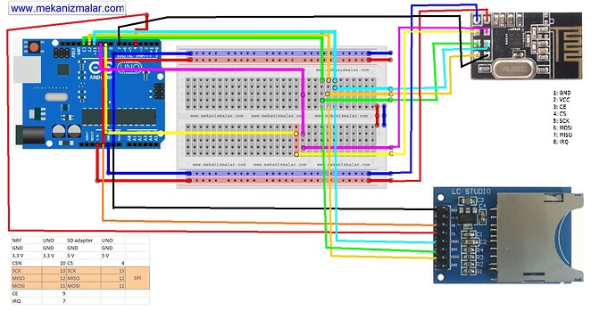
Transmission with only nRF24L01+ works. Same with only SD shield. Problem appers when i connect both of them. When i do this my STATUS register value is 0 (everytime when program starting it writes STATUS register value). It should be "E" default. It seems like SD card shield doesn't allow UNO to transfer vaules to nRF registers.

I tried with final code from this topic but without success: http://forum.arduino.cc/index.php/topic,80687.0.html.
I moved SD part of TX to RX and it work like i said before.

Schematic is under post.

Does anyone have idea how can i do it?

I am not sure if I understand what you are saying but if you are saying that you are trying to send or receive with more than one 433 Mhz module at the same time then they are probably both on the same frequency.(channel)

I want to send message "111" from Arduino Pro mini with nRf24L01+ (2.4GHz ISM freq) to Arduino UNO with nRF24L01+. After recive message Arduino Uno should write "111" to file on SD card.

Problem is: Why both can't work with SPI?

I've done this before . I think there is an example sketch in the RF24 Library that does exactly that.
Look at the Serial Test sketch in that library.

I actually think your SD card chip select might be conflicting with your radio chip select.

Thank you for fast reply and advice.

I don't see any sketch with name u write in RF24 examples and can't find it in the internet. Can u send me this code if u know where is it?

I agree with you that conflict with CS1 and CS2 is probably the main problem of my project.

I try to always have CSN pin LOW and after transmision with SPI set it to HIGH. TX send "111" after every 3 seconds and it works without SD adapter.

Here's my RX code maybe it makes my project clearly

/*********************************************************************
**   SPI-compatible                                                 **
**   CS - to digital pin 9  (CE pin)                                        **
**   CSN - to digital pin 10  (SS pin)                               **
**   MOSI - to digital pin 11 (MOSI pin)                            **
**   MISO - to digital pin 12 (MISO pin)                            **
**   CLK - to digital pin 13 (SCK pin)                              **
** CS2 SD - to digital pin 4                                 **
*********************************************************************/

#include <SD.h>
#include <SPI.h>
#include "API.h"
#include "nRF24L01.h"

File myFile;

//***************************************************
#define TX_ADR_WIDTH    5   // 5 unsigned chars TX(RX) address width
#define TX_PLOAD_WIDTH  32  // 32 unsigned chars TX payload

unsigned char TX_ADDRESS[TX_ADR_WIDTH]  = 
{
  0x34,0x43,0x10,0x10,0x01
}; // Define a static TX address

unsigned char rx_buf[TX_PLOAD_WIDTH] = {0}; // initialize value
unsigned char tx_buf[TX_PLOAD_WIDTH] = {0};
//***************************************************
void setup() 
{
  Serial.begin(57600);
  pinMode(CE,  OUTPUT);
  pinMode(CSN, OUTPUT);
  pinMode(IRQ, INPUT);
  SPI.begin();
  delay(50);
  init_io();                        // Initialize IO port
  unsigned char sstatus=SPI_Read(STATUS);
  Serial.println("*******************RX_Mode Start****************************");
  Serial.println("If no packet received, try to disconnect IRQ pin(10)");
  Serial.print("status = ");    
  Serial.println(sstatus,HEX);     // There is read the mode’s status register, the default value should be ‘E’
  RX_Mode();                        // set RX mode
  SD_Init();
}

void loop() 
{
  for(;;)
  {
    unsigned char status = SPI_Read(STATUS);                         // read register STATUS's value
    if(status&RX_DR)                                                 // if receive data ready (TX_DS) interrupt
    {
      SPI_Read_Buf(RD_RX_PLOAD, rx_buf, TX_PLOAD_WIDTH);             // read playload to rx_buf
      SPI_RW_Reg(FLUSH_RX,0);                                        // clear RX_FIFO
      for(int i=0; i<32; i++)
      {
          Serial.print(" ");
          Serial.print(rx_buf[i]);                              // print rx_buf
      }
      Serial.println(" ");
      SD_Write(1);                              // WRITE THING IN SD CARD
  }
    SPI_RW_Reg(WRITE_REG+STATUS,status);                            // clear RX_DR or TX_DS or MAX_RT interrupt flag
  }
}

//**************************************************
// Function: init_io();
// Description:
// flash led one time,chip enable(ready to TX or RX Mode),
// Spi disable,Spi clock line init high
//**************************************************
void init_io(void)
{
  digitalWrite(IRQ, 0);
  digitalWrite(CE, 0);			// chip enable
  digitalWrite(CSN, 1);                 // Spi disable	
}

/************************************************************************
**   * Function: SPI_RW();
 * 
 * Description:
 * Writes one unsigned char to nRF24L01, and return the unsigned char read
 * from nRF24L01 during write, according to SPI protocol
************************************************************************/
unsigned char SPI_RW(unsigned char Byte)
{
  return SPI.transfer(Byte);
}

/**************************************************/

/**************************************************
 * Function: SPI_RW_Reg();
 * 
 * Description:
 * Writes value 'value' to register 'reg'
/**************************************************/
unsigned char SPI_RW_Reg(unsigned char reg, unsigned char value)
{
  unsigned char status;

  digitalWrite(CSN, 0);                   // CSN low, init SPI transaction
  SPI_RW(reg);                            // select register
  SPI_RW(value);                          // ..and write value to it..
  digitalWrite(CSN, 1);                   // CSN high again

  return(status);                   // return nRF24L01 status unsigned char
}
/**************************************************/

/**************************************************
 * Function: SPI_Read();
 * 
 * Description:
 * Read one unsigned char from nRF24L01 register, 'reg'
/**************************************************/
unsigned char SPI_Read(unsigned char reg)
{
  unsigned char reg_val;

  digitalWrite(CSN, 0);                // CSN low, initialize SPI communication...
  SPI_RW(reg);                         // Select register to read from..
  reg_val = SPI_RW(0);                 // ..then read register value
  digitalWrite(CSN, 1);                // CSN high, terminate SPI communication

  return(reg_val);                     // return register value
}
/**************************************************/

/**************************************************
 * Function: SPI_Read_Buf();
 * 
 * Description:
 * Reads 'unsigned chars' #of unsigned chars from register 'reg'
 * Typically used to read RX payload, Rx/Tx address
/**************************************************/
unsigned char SPI_Read_Buf(unsigned char reg, unsigned char *pBuf, unsigned char bytes)
{
  unsigned char sstatus,i;

  digitalWrite(CSN, 0);                   // Set CSN low, init SPI tranaction
  sstatus = SPI_RW(reg);       	    // Select register to write to and read status unsigned char

  for(i=0;i<bytes;i++)
  {
    pBuf[i] = SPI_RW(0);    // Perform SPI_RW to read unsigned char from nRF24L01
  }

  digitalWrite(CSN, 1);                   // Set CSN high again

  return(sstatus);                  // return nRF24L01 status unsigned char
}
/**************************************************/

/**************************************************
 * Function: SPI_Write_Buf();
 * 
 * Description:
 * Writes contents of buffer '*pBuf' to nRF24L01
 * Typically used to write TX payload, Rx/Tx address
/**************************************************/
unsigned char SPI_Write_Buf(unsigned char reg, unsigned char *pBuf, unsigned char bytes)
{
  unsigned char sstatus,i;

  digitalWrite(CSN, 0);                   // Set CSN low, init SPI tranaction
  sstatus = SPI_RW(reg);             // Select register to write to and read status unsigned char
  for(i=0;i<bytes; i++)             // then write all unsigned char in buffer(*pBuf)
  {
    SPI_RW(*pBuf++);
  }
  digitalWrite(CSN, 1);                   // Set CSN high again
  return(sstatus);                  // return nRF24L01 status unsigned char
}
/**************************************************/

void RX_Mode(void)
{
  digitalWrite(CE, 0);
  
  SPI_Write_Buf(WRITE_REG + RX_ADDR_P0, TX_ADDRESS, TX_ADR_WIDTH); // Use the same address on the RX device as the TX device
  SPI_RW_Reg(WRITE_REG + EN_AA, 0x01);      // Enable Auto.Ack:Pipe0
  SPI_RW_Reg(WRITE_REG + EN_RXADDR, 0x01);  // Enable Pipe0
  SPI_RW_Reg(WRITE_REG + RF_CH, 40);        // Select RF channel 40
  SPI_RW_Reg(WRITE_REG + RX_PW_P0, TX_PLOAD_WIDTH); // Select same RX payload width as TX Payload width
  SPI_RW_Reg(WRITE_REG + RF_SETUP, 0x07);   // TX_PWR:0dBm, Datarate:2Mbps, LNA:HCURR
  SPI_RW_Reg(WRITE_REG + CONFIG, 0x0f);     // Set PWR_UP bit, enable CRC(2 unsigned chars) & Prim:RX. RX_DR enabled..
  digitalWrite(CE, 1);                             // Set CE pin high to enable RX device
  //  This device is now ready to receive one packet of 16 unsigned chars payload from a TX device sending to address
  //  '3443101001', with auto acknowledgment, retransmit count of 10, RF channel 40 and datarate = 2Mbps.
}
///////////////////// SD INIT
void SD_Init(void)
{
    
     //SD code
  Serial.print("Initializing SD card...");
  if (!SD.begin(4)) {
    Serial.println("initialization failed!");
    return;
  }
  Serial.println("initialization done.");
}
////////////// SAVE ON SD CARD
void SD_Write(int z)
{
  myFile = SD.open("example.txt", FILE_WRITE);
  if (myFile)
  {
  myFile.print("value : ");
  myFile.println(z);
  }
  else
  {
  Serial.println("blad otwarcia pliku");
  }  
}
and TX code:

#include <SPI.h>
#include "API.h"
#include "nRF24L01.h"

File myFile;

//***************************************************
#define TX_ADR_WIDTH    5   // 5 unsigned chars TX(RX) address width
#define TX_PLOAD_WIDTH  32  // 32 unsigned chars TX payload

unsigned char TX_ADDRESS[TX_ADR_WIDTH]  = 
{
  0x34,0x43,0x10,0x10,0x01
}; // Define a static TX address

unsigned char rx_buf[TX_PLOAD_WIDTH] = {0}; // initialize value
unsigned char tx_buf[TX_PLOAD_WIDTH] = {0};

unsigned char temp_buf[TX_PLOAD_WIDTH] = {0};
//***************************************************
void setup() 
{
  Serial.begin(57600);
  pinMode(CE,  OUTPUT);
  pinMode(CSN, OUTPUT);
  pinMode(IRQ, INPUT);
  SPI.begin();
  delay(50);
  init_io();                        // Initialize IO port
  unsigned char sstatus=SPI_Read(STATUS);
  Serial.println("*******************TX_Mode Start****************************");
  Serial.print("status = ");    
  Serial.println(sstatus,HEX);     // There is read the mode’s status register, the default value should be ‘E’
  TX_Mode();                       // set TX mode
}

void loop() 
{
  int k = 0;
  int j = 0;
  
  for(;;)
{
    for(int i=0; i<32; i++)
    {
        tx_buf[i] = j;
        j=j+1;
    }
    for(int i=0; i<32; i++)
    {
        Serial.print(tx_buf[i]);
    }    
    Serial.println("");       
    
    unsigned char sstatus = SPI_Read(STATUS);                   // read register STATUS's value
    if(sstatus&TX_DS)                                           // if receive data ready (TX_DS) interrupt
    {
      SPI_RW_Reg(FLUSH_TX,0);                                  
      SPI_Write_Buf(WR_TX_PLOAD,tx_buf,TX_PLOAD_WIDTH);       // write playload to TX_FIFO
    }
    if(sstatus&MAX_RT)                                         // if receive data ready (MAX_RT) interrupt, this is retransmit than  SETUP_RETR                          
    {
      SPI_RW_Reg(FLUSH_TX,0);
      SPI_Write_Buf(WR_TX_PLOAD,tx_buf,TX_PLOAD_WIDTH);      // disable standy-mode
    }
    SPI_RW_Reg(WRITE_REG+STATUS,sstatus);                     // clear RX_DR or TX_DS or MAX_RT interrupt flag
    delay(3000);
    
    j=0;
  }
}

//**************************************************
// Function: init_io();
// Description:
// flash led one time,chip enable(ready to TX or RX Mode),
// Spi disable,Spi clock line init high
//**************************************************
void init_io(void)
{
  digitalWrite(IRQ, 0);
  digitalWrite(CE, 0);			// chip enable
  digitalWrite(CSN, 1);                 // Spi disable	
}

/************************************************************************
**   * Function: SPI_RW();
 * 
 * Description:
 * Writes one unsigned char to nRF24L01, and return the unsigned char read
 * from nRF24L01 during write, according to SPI protocol
************************************************************************/
unsigned char SPI_RW(unsigned char Byte)
{
  return SPI.transfer(Byte);
}

/**************************************************/

/**************************************************
 * Function: SPI_RW_Reg();
 * 
 * Description:
 * Writes value 'value' to register 'reg'
/**************************************************/
unsigned char SPI_RW_Reg(unsigned char reg, unsigned char value)
{
  unsigned char status;

  digitalWrite(CSN, 0);                   // CSN low, init SPI transaction
  SPI_RW(reg);                            // select register
  SPI_RW(value);                          // ..and write value to it..
  digitalWrite(CSN, 1);                   // CSN high again

  return(status);                   // return nRF24L01 status unsigned char
}
/**************************************************/

/**************************************************
 * Function: SPI_Read();
 * 
 * Description:
 * Read one unsigned char from nRF24L01 register, 'reg'
/**************************************************/
unsigned char SPI_Read(unsigned char reg)
{
  unsigned char reg_val;

  digitalWrite(CSN, 0);                // CSN low, initialize SPI communication...
  SPI_RW(reg);                         // Select register to read from..
  reg_val = SPI_RW(0);                 // ..then read register value
  digitalWrite(CSN, 1);                // CSN high, terminate SPI communication

  return(reg_val);                     // return register value
}
/**************************************************/

/**************************************************
 * Function: SPI_Read_Buf();
 * 
 * Description:
 * Reads 'unsigned chars' #of unsigned chars from register 'reg'
 * Typically used to read RX payload, Rx/Tx address
/**************************************************/
unsigned char SPI_Read_Buf(unsigned char reg, unsigned char *pBuf, unsigned char bytes)
{
  unsigned char sstatus,i;

  digitalWrite(CSN, 0);                   // Set CSN low, init SPI tranaction
  sstatus = SPI_RW(reg);       	    // Select register to write to and read status unsigned char

  for(i=0;i<bytes;i++)
  {
    pBuf[i] = SPI_RW(0);    // Perform SPI_RW to read unsigned char from nRF24L01
  }

  digitalWrite(CSN, 1);                   // Set CSN high again

  return(sstatus);                  // return nRF24L01 status unsigned char
}
/**************************************************/

/**************************************************
 * Function: SPI_Write_Buf();
 * 
 * Description:
 * Writes contents of buffer '*pBuf' to nRF24L01
 * Typically used to write TX payload, Rx/Tx address
/**************************************************/
unsigned char SPI_Write_Buf(unsigned char reg, unsigned char *pBuf, unsigned char bytes)
{
  unsigned char sstatus,i;

  digitalWrite(CSN, 0);                   // Set CSN low, init SPI tranaction
  sstatus = SPI_RW(reg);             // Select register to write to and read status unsigned char
  for(i=0;i<bytes; i++)             // then write all unsigned char in buffer(*pBuf)
  {
    SPI_RW(*pBuf++);
  }
  digitalWrite(CSN, 1);                   // Set CSN high again
  return(sstatus);                  // return nRF24L01 status unsigned char
}
/**************************************************/

/**************************************************
 * Function: TX_Mode();
 * 
 * Description:
 * This function initializes one nRF24L01 device to
 * TX mode, set TX address, set RX address for auto.ack,
 * fill TX payload, select RF channel, datarate & TX pwr.
 * PWR_UP is set, CRC(2 unsigned chars) is enabled, & PRIM:TX.
 * 
 * ToDo: One high pulse(>10us) on CE will now send this
 * packet and expext an acknowledgment from the RX device.
 **************************************************/
void TX_Mode(void)
{
  digitalWrite(CE, 0);

  SPI_Write_Buf(WRITE_REG + TX_ADDR, TX_ADDRESS, TX_ADR_WIDTH);    // Writes TX_Address to nRF24L01
  SPI_Write_Buf(WRITE_REG + RX_ADDR_P0, TX_ADDRESS, TX_ADR_WIDTH); // RX_Addr0 same as TX_Adr for Auto.Ack

  SPI_RW_Reg(WRITE_REG + EN_AA, 0x01);      // Enable Auto.Ack:Pipe0
  SPI_RW_Reg(WRITE_REG + EN_RXADDR, 0x01);  // Enable Pipe0
  SPI_RW_Reg(WRITE_REG + SETUP_RETR, 0x1a); // 500us + 86us, 10 retrans...
  SPI_RW_Reg(WRITE_REG + RF_CH, 40);        // Select RF channel 40
  SPI_RW_Reg(WRITE_REG + RF_SETUP, 0x07);   // TX_PWR:0dBm, Datarate:2Mbps, LNA:HCURR
  SPI_RW_Reg(WRITE_REG + CONFIG, 0x0e);     // Set PWR_UP bit, enable CRC(2 unsigned chars) & Prim:TX. MAX_RT & TX_DS enabled..
  SPI_Write_Buf(WR_TX_PLOAD,tx_buf,TX_PLOAD_WIDTH);

  digitalWrite(CE, 1);
}

Have a look at this post. It looks they are doing something similar without SD.
http://forum.arduino.cc/index.php?topic=254699.0

RF24 LIB download link:

See attached screenshot of RF24 library examples.
Look at "....button_Tx" (6th from the top)
and RX (8th from the top)

I don't know if this is any help. I am not a programmer per se. My specialty is hardware so I really can't proofread your code.

Thank you for reply.

I saw these sketchs and tried it on my board. They work well but in my project I want to save data somewhere without PC.

Does anybody have idea where can i put my data without SD card? (I feel that saving it in MCU Flash isn't good idea).

Hi martinez, i would like to know if you manage to solve this problem, because i have the same one.

@MARTINIES is no longer a member of the Forum.

I suggest you start your own Topic and describe your problem from the start.

...R