Arduino wiring guidance needed please.

I am looking for some knowledgeable advice about wiring from you experts out there.

I am making a mimic panel for my model railway. It will control 10 traffic flows by switches. Each will will use up to 4 LEDs (only 2 at a time) to indicate status. So I need a total of 50 I/O pins. There are also a few other pins in use to communicate with the system controller.
I have bought a mega so there are plenty of pins and I intend to connect the switch inputs to the Analog pins on it.

My initial attempt has used 5 switches and 10 LEDs to get the software working but now I need to move to a more permanent solution in a box.
I used a small length of PCB board and I soldered connections from the PCB to the Arduino using single strand wire which plugs directly into the Arduino headers.
I am now making the box but when fitting the lid, which holds the switches and LEDs, I dropped it and one of the wires broke at the PCB and will need re-soldering.
The wires are also a bit of a mess as they are all individual short lengths and I am worried that if I try to do the same for the other 35 wires I need it will be horrible and prone to damage.

Can anyone recommend a relatively straightforward method of connecting to the Arduino in these circumstances. I would like to have the wiring colour coded such that I can easily tell which wires go with which traffic flow.
I don’t mind soldering but I like to keep at least one PCB space between adjacent rows as I’m not very good at it.

Thanks

Mike
Two thing to look into:

  1. the ATmega CPU can only supply 200 ma MAX at any one time. If you load that many I/O pins with led's and try to turn them on at one time the chip will likely over heat and eventually fail.

  2. There are "break out" boards that provide solder pads for the I/O pins. You might find one that will help you control all those wires.

John

Thanks for the concern John but I have asked a previous question about power requirements and come to the conclusion that with a maximum of 20 LEDs needing about 130mA at one time it should not be a problem.
I have thought about utilising a prototype board but I'm not sure it cures the fundamental problem.

Mike

Biscit42:
I used a small length of PCB board and I soldered connections from the PCB to the Arduino using single strand wire which plugs directly into the Arduino headers.

And there's the problem. Single strand wire is "connect once, never move" - and I am fascinated by the concept of "plugs directly into the Arduino headers". The point where the insulation was stripped becomes a weak point where on one side of that point, the insulation supports the wire and on the other, the solder does.

I should have thought using flexible (i.e., multi-strand) "rainbow" cable such as those available with "Dupont" connectors would have been more appropriate. You can solder the male pins into a PCB for a permanent approach but you must test every one of the Chinese pre-terminated wires first.

Thanks Paul
by 'test' do you mean a simple continuity test?
I have been using jumper cables with square housings that came with my initial Uno kit but most of the male ends are quite short and don't seem to locate firmly into the female headers on the Arduino. The stripped end of the single strand wire at least pushes in firmly so is usable for small projects but I am looking at getting something more permanent.
I have been researching a bit tonight and have come across Molex Wire-to-Board connectors and IDC connectors for ribbon cable. Is there a connector for direct attachment of this sort of wire to the Arduino?
I haven't spotted one yet.

Mike

Biscit42:
by 'test' do you mean a simple continuity test?

Yes. My favourite trick is to plug them in to a breadboard so that connections zigzag back and forth connecting them all in series and then use a LED and resistor to test continuity, if it does not work, break the chain up into segments until you locate the problem.

Biscit42:
I have been using jumper cables with square housings that came with my initial Uno kit but most of the male ends are quite short and don't seem to locate firmly into the female headers on the Arduino.

That is rather surprising.

Biscit42:
The stripped end of the single strand wire at least pushes in firmly so is usable for small projects but I am looking at getting something more permanent.

Even more surprising that the gauge of wire you would likely be using, fits when the Dupont pins do not! :astonished:

Biscit42:
I have been researching a bit tonight and have come across Molex Wire-to-Board connectors and IDC connectors for ribbon cable. Is there a connector for direct attachment of this sort of wire to the Arduino?

Standard IDC fittings plug directly into the dual row connectors on the Mega 2560 - that is what they are; a standard. Sacrificing one row would allow fitting them to the other connectors.

I agree with Paul, you should be using stranded wire.

By breakout board I was thinking of something like this:

Breakout

Solder stranded wires to the breakout board and ty wrap them to the board for strain relief. In addition, if you want you can also put the LED resistors on the breakout board making the LED end connection simpler.

I have been using (and recommend) silicone wire that I bought on ebay. wire It is stranded with a lot of strands for great flexibility.

I doubt you will find enough colors to completely color code each wire.

You didn't mention the connections for the led's. I'm not sure how far you want to get into the construction, Right now if I were to build something with as many wires as you have I would consider designing a PCB using Kicad. It's probably more than you want to do for this project but it would / could be real slick. Both the LED's and the Mega could be on one board. Just a thought.

Just a side note, I have a low opinion of the reliability of dupont jumpers made in China (or maybe anywhere). I think they are too fragile for a permanent application. And while testing is good, it only shows that the jumper is working at that point in time, it cannot attest to the reliability.

My experience is that the earlier mentioned rainbow cable fits tightly if you have multiple connections fitted next to each other.

You might however be better off with
1)
A proto shield that fits on the mega and solder wires to that.
2)
A Robotdyn Mega Pro or Inhaos mega2560 core; you can directly solder wires (through hole).

Paul__B:
Standard IDC fittings plug directly into the dual row connectors on the Mega 2560 - that is what they are; a standard. Sacrificing one row would allow fitting them to the other connectors.

Paul, you say, with emphasis, IDC conectors "b]are[/b]" a standard.

How does this square with RS Components website which lists IDC connectors with pitches from 0.64mm to 6.5mm? Hardly a standard.
Please explain which IDC fittings you would recommend for the Mega.

I suspect that you looked at the wrong headers. Can you provide a link?

Google idc header.

Standard 0.1 inch pitch. Modern ones 2 mm pitch.

Biscit42:
Paul, you say, with emphasis, IDC conectors "b]are[/b]" a standard.

How does this square with RS Components website which lists IDC connectors with pitches from 0.64mm to 6.5mm? Hardly a standard.
Please explain which IDC fittings you would recommend for the Mega.

2-row 0.1" pitch are absolutely dominant, other sizes are available, but are sold in much smaller quantities
for specialized purposes.
0.05" pitch ribbon cable is similarly dominant for the same reason, people standardize.

Yes, that's standard in my book, de-facto standard.

Thanks for the explanation Mark but it would be good if people explained rather than making statements which are unverifiable.
I am getting closer to a definitive solution. A company in the UK is giving me some advice on their products and the one they are recommending, which looks a good possibilty, is clearly marked as "non-standard" "non-returnable". By this I think they will make up cables specificaly to my requirements.
I will let the world know what my final working solution is for the benefit of other newbies who are struggling with the same isssue.
Could this topic be done as a Tutorial at the top of the forum by somebody who knows?
Mike

Another thing you may look into is matrixing all those LEDs. 50 LEDs can be controlled by just 15 pins (7x8 for total 56 points). Saves a lot of wiring, as just 50 wires go from the Arduino to the block of LEDs.

To reduce the wiring between the LED display and the Arduino even more, use a bunch of shift registers at the display side. Again you can matrix it (then you need 3 shift registers) but it adds software complexity, or you use dedicated connections and you need 7 of them. Shift registers are really cheap. Just a few wires to the Arduino for all those LEDs. You can use the same trick to read the switches.

For a permanent installation you'll have to solder your wires.

I did look at other options to drive the LEDs but the code when using individual wires is so simple and extendable I decided not to pursue those routes once I had measured that the Mega can provide enough power for the maximum 20 LEDs in use at one time.

Biscit42:
I did look at other options to drive the LEDs but the code when using individual wires is so simple and extendible

Rubbish!

I focused on the matter of the connectors before and failed to point out the blindingly obvious! You don't need a Mega2560 at all, and wiring a Nano (or if you do not need further programmability of USB interface, a Pro Mini) by soldering is more practical.

50 LEDs? Don't muck about with shift registers either.

The proper way to do it would be to use a MAX7219. This makes far more sense than worrying about drive current, resistors and loading of shift registers not designed for the job in the first place. The fact that the MAX7219 is actually intended to drive all of 64 LEDs is of no concern if you only use fewer and any extra expense is minor (click on the illustration) but you save on not using a Mega 2560 anyway.

Given that it involves your own wiring for the LEDs in any case, the sensible way to approach this is to buy a couple (just in case) of the rubbish MAX7219 matrix modules - as a kit - and assemble them without the actual matrix and sockets for same, using the PCB to wire to your own set of LEDs.

This gives you ridiculous available brightness (but totally controllable both as the maximum which is set by the single resistor and overall in steps by code) requiring no code to continuously multiplex the display; you only update the MAX7219s when you want to change the display and the interface is just three pins.

It truly is a waste of time and effort doing it any other way and the wiring is massively simplified - no more than sixteen wires ever go to any part of the assembly and with the area broken up into sections, something like four wires for a given four LEDs, five wires for six and so on. :grinning:

Good suggestion.

To save on having code running to do the multiplexing is why I suggested to use more shift registers, but this will do even better indeed. Much simpler to set up! Gotta remember it, sooner or later I'm bound to get a project that needs lots of individual LEDs :slight_smile:

Wow, the shouty opinionated attitude of Paul_B has reminded me why I don't normally join forums.

But since I am not stupid enough to think I know everything, I do feel the need to ask occasionally. So I will explain why I am doing it my way which I try to base on the KISS principle (Look it up).

To wvmarle : where did I ever say I needed multiplexing?

  1. There is nothing simpler than 1 LED = 1 wire/pin. The code for this is embodied in the Arduino Example Blink and is easily extended.

  2. 40 LEDs = 40 wires/pins and since in my code the Pin definition is embodied in a structure, as I'm adding LEDs the basic code isn't changing. So, providing the Mega can cope with the power requirment it is an excellent fit for what I want.

  3. With the best will in the world adding other bits of kit adds complexity whether it is be it a shift register or a super deluxe LED controller. Both would need code modifications e.g driver libraries, as well as any learning curve associated with them.
    The MAX7219 is a case which shows my point perfectly. In the interests of fair play I looked at the website for this
    Mixed-signal and digital signal processing ICs | Analog Devices
    Although the description says that it will drive up to 64 individual LEDs its prime purpose is to drive an LED matrix. There is no explanation on the webpage how to drive the individual LEDS so using it would involve trawling around the net looking for how other people do it. Trying not to get caught by the aforementioned "rubbish" kits which would just cause extra angst. Finding suitable code, testing and incorporating into my code all before any final wiring can take place.

YUK
KISS rules

Multiplexing is a trade-off. You never said you need it, you also never said you don't want it. You never mentioned it even.

You need MUCH less wiring (a bundle of 40+ wires between your Mega and the LEDs, plus a current limiting resistor at each LED) at the expense of slightly more complex code.

Also a Mega can not handle 40 LEDs. Too much total current.

So for this application, multiplexing is the KISS solution.

Biscit42:
Although the description says that it will drive up to 64 individual LEDs its prime purpose is to drive an LED matrix. There is no explanation on the webpage how to drive the individual LEDS so using it would involve trawling around the net looking for how other people do it. Trying not to get caught by the aforementioned "rubbish" kits which would just cause extra angst. Finding suitable code, testing and incorporating into my code all before any final wiring can take place.

Oh dear! :roll_eyes:

Yes, the primary purpose of the MAX7219 is to drive a LED matrix.

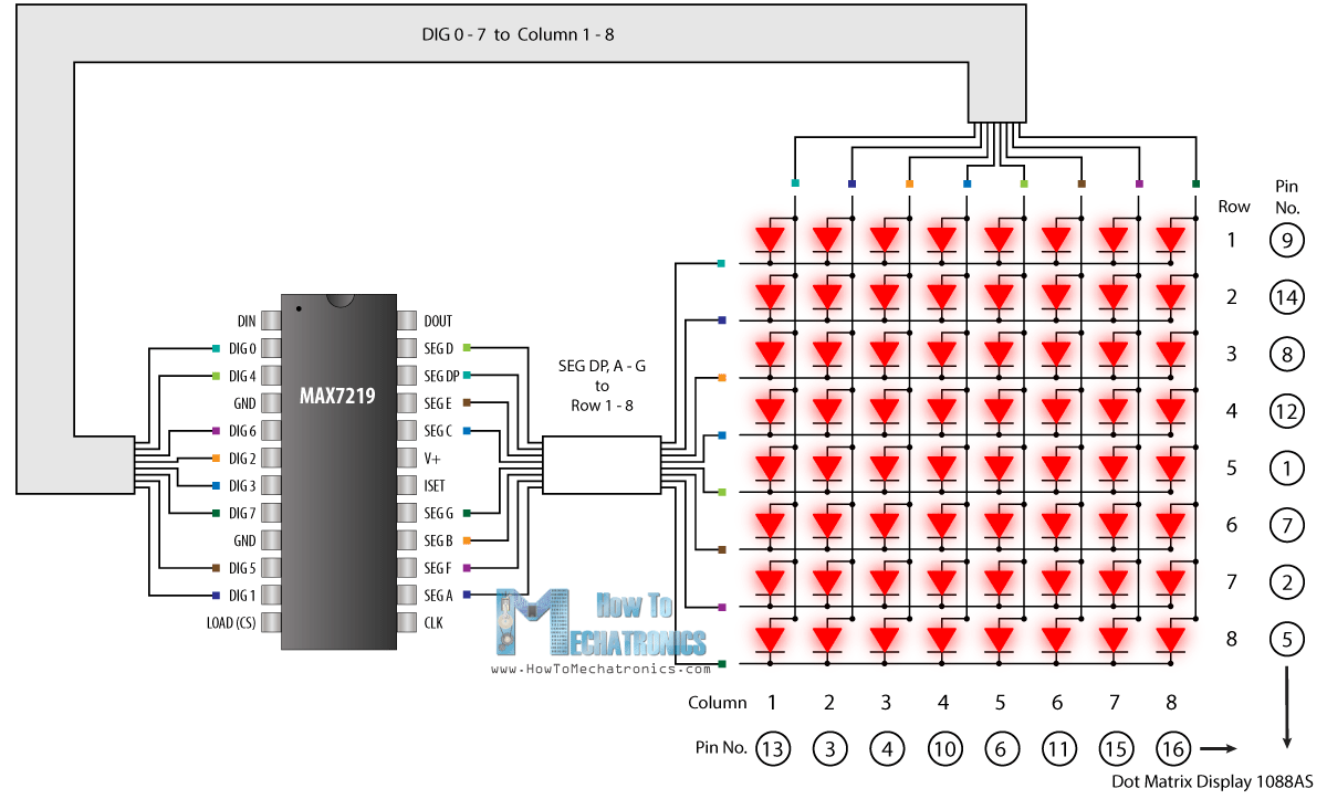
So your situation resolves to not comprehending what a LED matrix is. OK, I will find you an illustration (using Google).


Click to enlarge

There you are! A diagram of a LED matrix, and how it is connected to a MAX7219. The "pin Nos." refer to a particular, common matrix display component which is most likely the exact one illustrated in my previous post. So this matrix display is 64 LEDs mounted in a square array on a small PCB, encapsulated and provided with a "light pipe" overlay for the situation where you want to display patterns. Fine. But all it is, is 64 LEDs connected in a certain manner such that each one has its anode connected to one of eight "SEG" lines, and its cathode connected to one of eight "DIG" lines and no two LEDs connect to the same pair.

Now here is the brilliant bit! The LEDs do not have to be sitting beside each other. This is the magic of wiring! You can take each LED, connected to its two wires, and extend them to any part of a model railway layout or other display. I explained before that this permits you to extend the absolute minimum number of wires to groups of LEDs instead of one wire per LED plus one common wire. So your wiring loom is seriously simplified.

As to the code, the implication is that the state of up to sixty-four LEDs is kept in eight consecutive bytes - 8 bits each. A simple code module - for which you only have to ask here on this forum, transfers these eight bytes (or just one of them if that is all that is needed) over the three wire interface to the MAX7219.


So, you have picked up on my reference to "rubbish" kits. Since you mention it, here is the rest of the explanation, directed to those who do want to use such matrix modules for moving message boards, which clearly does not apply to yourself.


So why did I call the modules "rubbish"? Because using these modules with the original matrix displays makes them entirely impractical to stack which is what most people want to do - if you wish to do this you would use the proper design instead. :grinning:

In fact, if you were actually creating a serious display such as for a game, you might even consider upgrading to a more sophisticated but relatively inexpensive display using MAX7219 (stackable further) modules:

wvmarle. ---- If you had read the rest of the post you would have realised that there will NEVER be 40 LEDs on at one time. The maximum is <20 and I have already determined that the Mega can handle this.

I am also failing to see how quote "each LED, connected to its two wires" can possibly be better than 1 wire per LED with a common GND bus and "seriously simplify the wiring loom".