2293Hz from RADAR_INPUT

1 Like

Thank you both for running the FFT. Closely matching results. I also was able to run an FFT on the signal, albeit not with my MCU board's ADC, but with Audacity. Audacity, (was not aware) under Analyze -> Plot Spectrum has several FFT options. I used the same as the ArduinoFFT on my MCU board (Hamming window), and also set it for 44.1kHz and 256 samples. (Memo for record: "rectangular" and "linear" gave much more concise peaks)
Before I list my findings, I am more convinced that:
-
Most likely: the input signal to my MCU's ADC pin is not strong enough (attenuated incorrectly). Should I add a signal buffer op amp before the ADC pin? Or should I change the 1.18K Ohm / 2.18K Ohm voltage divider resistors to like 6M Ohm/10M Ohm?
-
The other likely possibility (much less likely) is that my MCU's ADC setup somehow is not fast enough to sample, even at the 8bit setting and only 256 samples.
-
Least likely: the signal period is too short for my FFT sampling-setup settings and only captures a fraction of a full wave.
My test setup:

What I did to measure the RADAR-INPUT signal I posted here previously:
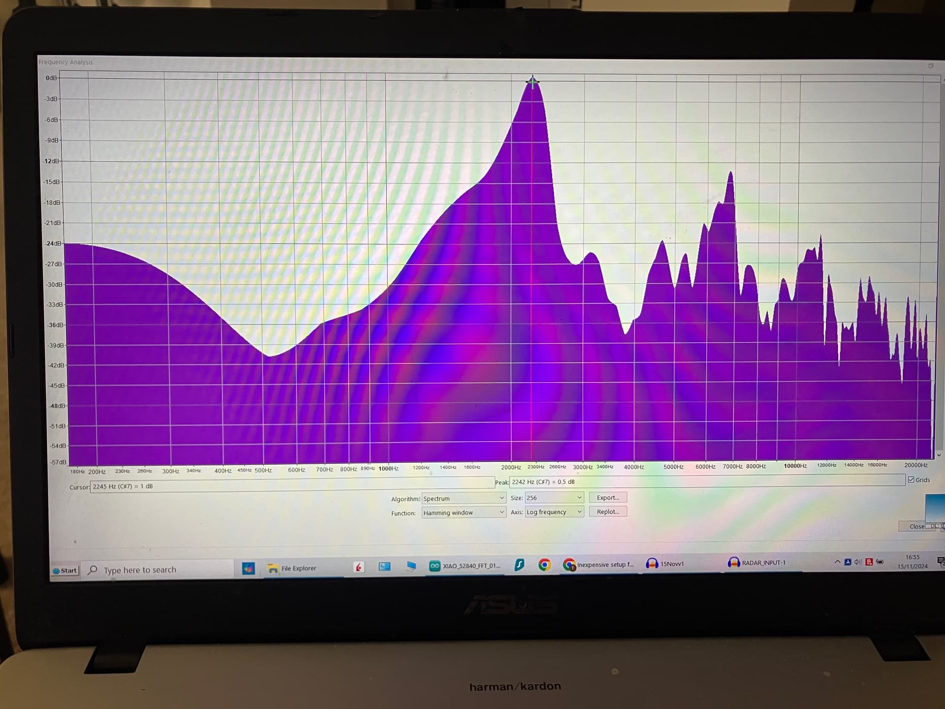
1. Used Audacity to run an FFT on it as described above. Result: peak Freq 2245 Hz. I zoomed in on the peaks section and used that for sampling. Very close to both of yours result, good enough for 256 sampling bins at 44.1khz (172Hz wide bins)
2. Then used Audacity to play the recorded signal back via my laptop's USB dongle AUDIO-OUT connected to GND and ADC pin of my MCU with the down-converted 1.58V DC idle signal also coming from the radar's op amp and also connected to the oscope.
The oscope measured:
1ms scale -> 2110Hz
500us scale -> 2260Hz
250us scale -> 2290 Hz
100us scale -> 2260Hz
50us scale -> 2240Hz
(close enough)
3. At the same time I had the ADC running on my MCU with the code posted below while I played the RADAR INPUT signal via the USB dongle and radar turned on on idle. And I was not getting any readings on the serial port in Arduino IDE. But, if I waved my hand in front of the radar sensor...then it registered reasonably corresponding Hertz readings on the serial port of the Arduino IDE while connected to my MCU's ADC. Then I connected the oscope's 1 Khz continuous signal to my MCU's ADC's pin and the Arduino IDE serial port connected to my MCU started to read 1270Hz-1290Hz. Which is off by about 270Hz from the actual 1000Hz input, but the readings are consistent...so will not try to fix that now.
RADAR INPUT signal FFT-analyzed by Audacity:
Selected signal span to play back via Audacity:

Here is my current FFT code based on ArduinoFFT running on nRF52840 Cortex M4:
/*

	Example of use of the FFT library

  Copyright (C) 2014 Enrique Condes
  Copyright (C) 2020 Bim Overbohm (template, speed improvements)

	This program is free software: you can redistribute it and/or modify
	it under the terms of the GNU General Public License as published by
	the Free Software Foundation, either version 3 of the License, or
	(at your option) any later version.

	This program is distributed in the hope that it will be useful,
	but WITHOUT ANY WARRANTY; without even the implied warranty of
	MERCHANTABILITY or FITNESS FOR A PARTICULAR PURPOSE.  See the
	GNU General Public License for more details.

	You should have received a copy of the GNU General Public License
	along with this program.  If not, see <http://www.gnu.org/licenses/>.

*/

/*
  In this example, the Arduino simulates the sampling of a sinusoidal 1000 Hz
  signal with an amplitude of 100, sampled at 5000 Hz. Samples are stored
  inside the vReal array. The samples are windowed according to Hamming
  function. The FFT is computed using the windowed samples. Then the magnitudes
  of each of the frequencies that compose the signal are calculated. Finally,
  the frequency with the highest peak is obtained, being that the main frequency
  present in the signal.

  USe a buffer to save the ADC read???   Recreate the wave and see if matches.
*/

#include "arduinoFFT.h"

/*
These values can be changed in order to evaluate the functions
*/
const uint16_t samples = 256; //This value MUST ALWAYS be a power of 2
 double signalFrequency;
const double samplingFrequency = 44100;
const uint8_t amplitude = 1;

/*
These are the input and output vectors
Input vectors receive computed results from FFT
*/
double vReal[samples];
double vImag[samples];

/* Create FFT object */
ArduinoFFT<double> FFT = ArduinoFFT<double>(vReal, vImag, samples, samplingFrequency);

#define SCL_INDEX 0x00
#define SCL_TIME 0x01
#define SCL_FREQUENCY 0x02
#define SCL_PLOT 0x03

void setup()
{
  Serial.begin(115200);
//  while(!Serial);
 // Serial.println("Ready");


// Set the resolution to 12-bit (0..4095)
  analogReadResolution(8); // Can be 8, 10, 12 or 14

  // Set the analog reference to 2.4V (default = 3.6V)
  analogReference(AR_VDD);  //signal threshold on oscope is 1.2V
/*
AR_VDD: the default 3.3 V reference
AR_INTERNAL: built-in 0.6 V reference
AR_INTERNAL1V2: 1.2 V reference (internal 0.6 V reference with 2x gain)
AR_INTERNAL2V4: 2.4 V reference (internal 0.6 V reference with 4x gain)
*/

}

void loop()
{
  /* Build raw data */

//double ratio = (twoPi * signalFrequency) / samplingFrequency; // Fraction of a complete cycle stored at each sample (in radians)
//double ratio = (twoPi * analogRead(A0)) / samplingFrequency; // Fraction of a complete cycle stored at each sample (in radians)
  //double ratio = analogRead(A0);
 // Serial.print("ratio :");Serial.println(ratio);
  for (uint16_t i = 0; i < samples; i++)
  {
   //vReal[i] = i * ratio;/* Build data with positive and negative values*/
    vReal[i] = analogRead(A0);
    //vReal[i] = int8_t(amplitude * sin(i * ratio) / 2.0);/* Build data with positive and negative values*/
    //vReal[i] = uint8_t((amplitude * (sin(i * ratio) + 1.0)) / 2.0);/* Build data displaced on the Y axis to include only positive values*/
    vImag[i] = 0.0; //Imaginary part must be zeroed in case of looping to avoid wrong calculations and overflows
  }
  /* Print the results of the simulated sampling according to time */
// Serial.println("Data:");
 //PrintVector(vReal, samples, SCL_TIME);
 FFT.windowing(FFTWindow::Hamming, FFTDirection::Forward);	/* Weigh data */
 // Serial.println("Weighed data:");
 // PrintVector(vReal, samples, SCL_TIME);
  FFT.compute(FFTDirection::Forward); /* Compute FFT */
 // Serial.println("Computed Real values:");
 // PrintVector(vReal, samples, SCL_INDEX);
 // Serial.println("Computed Imaginary values:");
 // PrintVector(vImag, samples, SCL_INDEX);
  FFT.complexToMagnitude(); /* Compute magnitudes */
//  Serial.println("Computed magnitudes:");
 // PrintVector(vReal, (samples >> 1), SCL_FREQUENCY);
  double x = FFT.majorPeak();
 if (x > 175) {
  Serial.println(x, 2);
  }
 // while(1); /* Run Once */
  // delay(2000); /* Repeat after delay */
}

void PrintVector(double *vData, uint16_t bufferSize, uint8_t scaleType)
{
  for (uint16_t i = 0; i < bufferSize; i++)
  {
    double abscissa;
    /* Print abscissa value */
    switch (scaleType)
    {
      case SCL_INDEX:
        abscissa = (i * 1.0);
	break;
      case SCL_TIME:
        abscissa = ((i * 1.0) / samplingFrequency);
	break;
      case SCL_FREQUENCY:
        abscissa = ((i * 1.0 * samplingFrequency) / samples);
	break;
    }
    Serial.print(abscissa, 6);
    if(scaleType==SCL_FREQUENCY)
      Serial.print("Hz");
    Serial.print(" ");
    Serial.println(vData[i], 4);
  }
  Serial.println();
}
You are still running blind since you don't know the High pass and Low Pass cutoff frequencies of your circuit or your actual sample rate.
If that circuit is from some motion detecting device I would guess the Low pass is 50Hz or less and the High Pass at most 5kHz. I would cut the trace right before C34 and add an op-amp circuit with adjustable gain and offset to the output of U2.
You need to run a test on you nRF52 to find the actual sample rate.
I see that the teensy is great for doing audio dsp.
The circuit resides on a radar chronograph device that measures the velocity of projectiles like nerf, pellets, bullets, etc from 20 fps to 1200 fps. These velocities were tested by feeding a steady 50% duty cycle signal from 0 Hz to 30 Khz with the sensor removed and replaced by a FREQ generator. The low-pass is at about 25Khz and the high-pass is about 500 Hz. The low-pass is probably are also coded in the firmware.
The radar device code (based on the accompanying iOS app) has several setting bands for the expected velocity to be measured. This has to be done by the user, or the radar will NOT register any readings if the actual velocity of the projectile is outside of these set limits. For example, the so called "nerf setting" is between 20-160fps, the "bow/airsoft" is 147fps-459fps, etc. I am sure these velocity tiers are there in order for the code to be able to sample with the best accuracy by keeping the maximum expected freq sampling rate as close to the Nyquist number as possible while maintaining the same sample size.
As you advised, I am considering adding a buffer op amp/adj gain op amp between test point A3 (after the second op amp) to my board's ADC. I suspect an impedance match issue, which I need to still read up on to understand better.
The MCU (and its ADC) on my board are near identical to the one used by the actual radar device's MCU/ADC, but do not know if the radar device is running its ADC in SAADC mode set at the chip's max 200 kHz sampling rate. I need to test my ADC also, since I am using it in the Arduino IDE and not in its native C++ IDE like Segger, Kiel, etc. which has a lot more commands and setup tweaks.
And ArduinoFFT may not be setup to use the optimized processing, interrupts, sampling, ect that the native C++ IDE environment is able to provide in FFT/ SAADC processing for this Cortex M4 MCU.
Also, I am using Serial.print in Aurdio IDE when testing which may be impeding my ADC sampling speed and MCU speed.
And also do not know, if they are using a differential ADC/SAADC setup. The radar's SAADC has the sensor signal's input on AIN0 pin and a separate 2.5VDC signal input on AIN1 pin. The AIN0 signal input seems to be AC from 0V-5VAC which you already pointed is not good for the chip, but that's how the actual PCB board is setup in this radar device.
As I mentioned before in post #71, do not know if this is setup as a differential SAADC or the AIN1 is a reference voltage to compensate for any circuit voltage variations that my affect AIN0 also.
Yes, Teensy has some great audio libraries and also a passionate following.
On Saturday, I received my Teensy 4.0 and I also bought the PJRC Audio Shield Rev. D. PJRC Store With this 600 Mhz chip I want to make sure I eliminate any possibility of slow ADC samplings. At least until I figure out why the (near) same MCU on my board does not read properly the same input signal that the radar MCU is able to process just fine.
When you are sampling with your MCU, the other MCU is also sampling at the same time? I don't know if this could be a problem, but anyway if you add an opamp to buffer the signal it should be fine. You could also add an RC filter, at least the low-pass filter.
Check the voltage ranges of the opamp. I think that this one could work: mcp6022. It's input and output rail to rail, and there is a DIP version.
With an STM32F4, cortex M4, I can sample at 350KHz without problems, but using the DMA to send the ADC data to memory directly.
Without seeing the code you may never know. Also, what the Arduino IDE allows you to do with the ADC is extremely limited.
1 Like
Yes, I have the radar device's on board MCU and my own MCU connected to the on board op amp at the same time. Both are using ADC 0, but I don't have the code of the radar device's setup.
Made some good progress. Using the Teensy 4.0 and its Audio shield with one of the Teensy example FFT codes, I was able to measure consistent correct readings from the first try. I only tried up to about 2.2khz and I had to manually check the bins first, but every reading was consistent. I used Audacity to playback a recorded actual radar device signal, and then the actual radar device signal as the input in real-time.
Apparently, the Teensy code is optimized for that board and for the FFT task, and takes advantage of the powerful 600Mhz CPU and its ADC. The example code I used and slightly modified is mostly hard-coded at 1024 samples (512 used), at 44.1Khz rate. I had no issues reading the signal consistently with and without the matching Audio Shield. The signal will need some adjusting, if I use the Audio shield, because it expects audio input ranges, 1Vpp.
I made some attempts at coding to print the major peak frequency instead of having to manually locating it, got it working, but did not have enough time to get it right yet. (I was not able to find one such example yet from the Teensy library that does that, which is strange)
Related to this: not surprising, but something I need to examine more: the oscope-measured freq value is an average based on the length of the signal burst and based on the period of the measuring window. For example, at 1ms sampling window I can have an overall 1850 Hz signal, but if I "zoom" in to the 500us window on the oscope then it reads 1890 Hz, and at 250us 1920Hz, then after about 100us no signal.
So if I get a 1920Hz read on my FFT from the MCU, it is still technically correct, if the sampling window was set at 250us. The true freq can be eventually resolved, I do have a chronograph that I can calibrate to the readings of the radar device and I can adjust the sampling window and averaging if needed. Later on this..
Which brings me back to why I was not able to get consistent readings when using Arduino IDE and the other MCU which is a Cortex M4? Obviously, the radar device has the same MCU/ADC as mine and that works. My guess at this point is that the radar device's nRF52 ADC is surely coded to run at full max speed of 200 Khz, and the sampling size is probably at east 1024. Both the ADC and FFT codes are not the vanilla "one size fits" Arduino IDE FFT, but "native" C++ CMSIS DSP FFT.
Also, in my case, this is a non-periodic signal. I had no real problems with the ArduinoFFT with continuous periodic signals, but non-periodic short bursts is what seems to be the problem. The ArduinoFFT is just not fast enough or not "windowed" properly to reliably detect a few millisecond long burst.
I will do some ADC cycle time tests for the Teensy and will compare it with the nRF52. Clearly the nRF52 can be made work with the sort burst that work with the Teensy, but likely will need to use the native C++ Nordic SDK (via Segger, Kiel) and the CMSIS DSP library. The issue with Teensy that prevents me to consider it for a final battery project solution, is that it uses 100mA power vs the 2-3mA of the nRF52 and that is with BLE running! Even at lower CPU speeds, the Teensy is multitudes more of an energy hog than the nRf52.
But for now, beggars should not be choosy, so I will continue with the Teensy on this project until I get it all sorted out before I jump deep into Segger Studio and the nRF52. Will try to dig into the hard coded Teensy library files to see if I can get the max 4096 sample size and if I can increase the sampling rate to 200Khz or more for the ADC. I think the Teensy can do 150Mhz clocks, but do not know how much of that translates into ADC speed.
////////////////////////////////////////////////////////////////////////////////////////
This is an older non-windowed FFT version that uses the Teensy pins directly. I need to recode the other official Teensy example program to use pins since that is coded for the Audio Shield.
//teensy 4.0  gives you FFT of an audio signal on analog pin A2/ pin 16
//This will work without the audio shield present, but I2S output (or any other I/O object that causes the library to update) is currently required. Future versions will remove this requirement

#include <Audio.h>

// GUItool: begin automatically generated code
AudioInputAnalog         adc1;           //xy=197,73
AudioAnalyzeFFT1024      fft1024_1;      //xy=361,47
AudioOutputI2S           i2s1;           //xy=378,99
AudioConnection          patchCord1(adc1, 0, i2s1, 0);
AudioConnection          patchCord2(adc1, 0, i2s1, 1);
AudioConnection          patchCord3(adc1, fft1024_1);
AudioControlSGTL5000     sgtl5000_1;     //xy=265,161
// GUItool: end automatically generated code

void setup() {
  AudioMemory(30);
  sgtl5000_1.enable();
  sgtl5000_1.volume(0.5);
  while (!Serial) ; // wait for Arduino Serial Monitor
  //Serial.println("FFT test");
}

void loop() {
float domfreq;
  float n;
float majorpeak=0;

  if (fft1024_1.available()) {
    for (int i=0; i < 60; i++) {  // print the first 60 bins to 2580 Hz from a max of 22Khz.
    n = (fft1024_1.read(i));
    if (n >= 0.01) {
      if (n > majorpeak) {
        majorpeak= n;
        domfreq = (i*43.0664);

           }
          Serial.print(n); Serial.print("<");Serial.print(i*43.0664);  Serial.print("Hz ");
       }  else {
        Serial.print("     -     ");
       }
    }
    Serial.print(domfreq,2), Serial.println("Hz |");majorpeak=0;domfreq=0;
  }
}
Doesn't matter. The DFT is based on the assumption that the signal is periodic.
The actual DFT of a non-periodic signal would require an infinite number of samples.
Happy Thanksgiving!
After the fairly decent readings (albeit not consistent) by the Teensy 4.0 and its Audio shield at below 5 Khz signals, I tried a Raspberry Pico W (RP2040). Found a working ADC + FFT code using C++/MicroPython. The max ADC is 500 kHz on this one and I tested it all the way up to 100 Khz with my cheapo Ebay Chinese frequency generator PCB gadget. Also with my precise oscope 1 Khz signal. I am using Microsoft VS with the Raspberry PI Pico Project extension. Setup was fairly uncomplicated ( even for me) and was able to play around the ADC clock, sample rates, sample sizes.
But the RP2040 ADC is all over the place when the ADC pin is floating, or if connected to a signal source and no signal yet coming through. Using Audacity and a USB audio dongle output playing the actual recorded doppler signal from the doppler radar gadget itself, the RP2040 correctly identifies the frequency (within about 1-2% of the oscope). The recorded signal is about 7 seconds long with a 1.3 Khz spike in the middle of that time span. Before I play that signal, the ADC readings gyrate all the way up between 500 hz (my cutoff) to the tens of thousands of hertz. As soon as I start playing the signal into the ADC, the ADC readings stop (must have fallen below my 500 Hz filter) and when the signal reaches the 1.3Khz spike in the recording it properly reads and displays that 1.3Khz value. Then the ADC stay still again until the last few seconds of the signal play and when finished...the ADC readings jump all over again between 500hz and tens of thousands.
Going back to the radar device itself....when I tapped into the doppler radar gadget's op amp output (still connected to its own MCU's SAADC), I even added a non-inverting Schmitt buffer (memo for self: need to make it an inverter) to see if that would provide some stability and eliminate any signal strength possibilities. Albeit the oscope registered clear square signals, my own board's ADC was all over the place drowning out the correct
reading.
So I am now reading up on the importance (and calculation) of output impedance and input impedance, Also checking into the RP2040's ADC input stability. According to the datasheet, it uses a 1pf capacitor and the effective impedance is 100 Khz. I am using the default ADC supply voltage which is not that stable based on what I read. Although an external VREF is recommended for absolute accuracy, I am not talking about a few mV difference in readings, but readings that gyrate between 50 hz and 20,000 hz every few hundred millisec periods...at times even up to 40-60,000 hz. I think the MircoPython code ADC range at full 3.3V scale goes up to 64K (16 bit) while in C++ it's 4096 (12-bit).
So with several boards and two types of FFTs algos tested (arm.math and ArduinoFFT), I am quite certain that I have some impedance matching issues, and some ADC input signal coding/conditioning.
Tasks:
- calculate impedance out/in to ADC
- read up on the RP20240 ADC stablity (pullup/pulldown pin?, ext. VREF?, etc)
- build my own op amp circuit and not rely on sharing the op amp output signal with the radar device's own MCU SAADC circuit.
Most ADC inputs work best when driven by a low source impedance such as the output of an op-amp. Impedance matching does not come into the picture in this application. You might want to concentrate on filtering the signal before the ADC. The more noise you can remove the bettor.
2 Likes
Impedance is measured in ohms not hz?
Yes, my error. 100 Kohms
Well, I have come a full circle to analog design. As Jim and others advised from the get-go, must make sure that there is a good signal to the ADC. I have a couple of FFT solutions ready to go finally with upto 250 Khz rate, but they suffer from a poor signal source that I "stole" from the radar device gadget's PCB. So, now will build my own op amp circuit board.
Below is what I believe should work for these specs (had these already at home):
3.3V supply
Freq operating range: 500 Hz - 100 Khz
Sensor: -0.3/+0.3V DC
High-pass: about 500 Hz (100 Ohm / 3uF)
Low-pass: 159 kHZ (100 Ohm / 1nF and 100 Ohm / 100pf)
Bandwidth: 100 kHz at +20 dBa
OP AMP Gain: 1000x (100/1K and 100/10k)
For prototype PCB will use the TI Dual-DIY EVAL AMPS012A inverting dual op amp template. https://www.ti.com/lit/ug/sbou193/sbou193.pdf?ts=1733621255320&ref_url=https%253A%252F%252Fwww.ti.com%252Ftool%252FDUAL-DIYAMP-EVM
Chosen the OPA2836, a low-power (1mA) dual op amp with 205 GBW, 560V/us fast slew rate, R-to-R. I know, it's several times overkill, but I had it already at home.
EDIT: the typical radar sensor has some caveats: "On top of that you may amplify this offset voltage by DC-coupling, however not more than by a factor of 10 (20dB), otherwise the following amplifier will be driven into saturation. From there on any amplification must be performed by AC-coupling ...the very last 40 or 50 db of gain can only be generated by an AC-coupled approach..."
EDIT 2: " In general a total line-up amplification of 60 to 70 dB is required in order to bring a receiver signal of a few 100 μV’s right at the mixer output to a level of 1 to 2 Vpp, depending if you want to end up in a limited or a linearly amplified LF signal. As basic amplifier circuits you may use inverting or high-impedance non-inverting amplifier circuits. To guarantee lowest noise contribution you should select appropriate opamps. Note: Avoid high ohmic resistor values in your feedback paths for noise contribution reasons. Gain your required amplifier gain by lowering the values of your interstage coupling resistors."
FIRST STAGE:


SECOND STAGE:


Did not forget, just things are on hold for the holidays.
The proper analog front-end build seems to be the key, as I am realizing now (and as advised by you previously) that breadboards, alligator clip wires, etc are not a reliable way to test a setup for these RF parameters.
This topic was automatically closed 180 days after the last reply. New replies are no longer allowed.