Hello all,
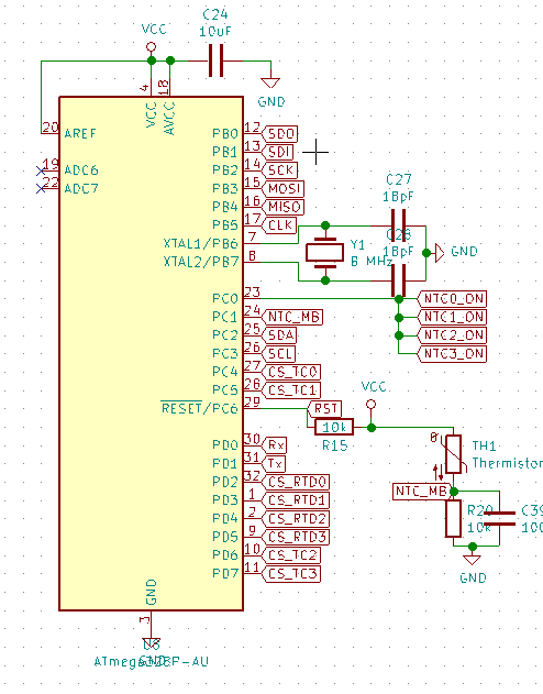
I am in a seriously strange situation. I have designed a temperature logging PCB with an ATMega328-AU chip to interface to the temp ICs.
I have uploaded the Atmega328P bootloader, so that I can use the arduino IDE and framework and libraries.
This was done by changing the ID for 328 to the ID of 328p in the avrdude.conf file.
According to the datasheet and pinout images found online, the pinout should be identical for the 328 and 328P chips.

I have had problems communicating to the ICs on the board via software SPI, so I have written a basic pin on/off program to check that everything works as expected.
But when I define 2 pins, PB0 (SDO, Arduino pin 8) and PB2 (SCK, Arduino pin 11) as outputs and flip them with a 1 s delay, it is not those pins that flip, according the pinout above.
Instead it is PD2 (pin 2) and PD0 (pin 0) which flips!
This is my code:
int sdo = PB0;
int sck = PB2;

void setup() {
pinMode(sdo, OUTPUT);
pinMode(sck,OUTPUT);
}
void loop() {
digitalWrite(sdo, HIGH);
digitalWrite(sck, HIGH);
delay(500);
digitalWrite(sdo, LOW);
digitalWrite(sck, LOW);
delay(500);
}
Can someone explain what is going on here? I have attached the schematic for the MCU.