Hello
I need some help, since I am not sure if I can do my current project/idea.
I would like to controll a fan (if possible more fans) with my attiny 202.
Additional it should be able to communicate with I2C (it sends the speed of the fan to another microcontorller and receives its configuration/targetspeed over the I2C bus.)
PWM is usually generated by hardware insixe the controller.
Please post a link to the datasheet of the fan motor.
No time to read 2 other projects. Please extract the information that describes exactly what You aim for.
Yes exactly I would like to generate PWM-Signal with the Attiny.
The PWM-signal can be changed by receiving data over I2C by another controller or something that uses I2C, exactly as your picture shows it. Additional I would like that the Attiny uses the tacho-pin so it can calculate the current RPM and send it over I2C to know of the fan is spinning and how fast.
I currently got a fan controlled by pcb which normaly controlls (stepper?) motors. Now I would like to use PWM instead of the voltage to controll the speed.
The plan is to replace the pcb with a direct connection to the fan (5V USB ->12V stepup converter -> 12V fan).
And the Attiny gets connected to the 5V or if needed a 3.3V voltage regulator (USB -> Attiny).
The PWM pin and the tacho pin of the fan is connected to the attiny.
For sure You need some kind of driver to handle a 12 volt fan. A simple logic level N channel MOSFET transistor, and 2 resistors would do it.
Check what that tacho output delivers, how the output is done. 12 volt is no, no.
This was the code which I would like to use (first I tought that I hadt to use only the avr stuff but I noticed I can use arduino since the memory consuption is not too high)
#include <Arduino.h>
#include <Wire.h>

#define FAN_PIN 2
#define TACHO_PIN 3
#define FS_ADDR 0x01
uint16_t fanSpeed = 0;
uint16_t tachoReading = 0;
int rpm;

void getTacho()
{
  Wire.write(tachoReading);
}

void setSpeed(int numbOfBytes)
{
  if (numbOfBytes == 1)
  {
    if (Wire.available())
    { // Read received data
      fanSpeed = Wire.read();
    }
  }

  analogWrite(FAN_PIN, fanSpeed);
}

void countup() {
  fanSpeed++;
}

void meassure() {
  fanSpeed = 0;
  attachInterrupt(digitalPinToInterrupt(TACHO_PIN), countup, RISING);
  delay(1000);
  detachInterrupt(digitalPinToInterrupt(TACHO_PIN));
  rpm = (fanSpeed / 2) * 60;

}

I hope that shows what I would like to do :D


void setup()
{
  // Setup pwm fan
  pinMode(FAN_PIN, OUTPUT);
  analogWrite(FAN_PIN, fanSpeed);
  // Setup tacho pin
  pinMode(TACHO_PIN, INPUT);

  // Init i2c
  Wire.begin(0x20);
  Wire.onRequest(getTacho);
  Wire.onReceive(setSpeed);
}

void loop()
{
  meassure();
}
Just great!
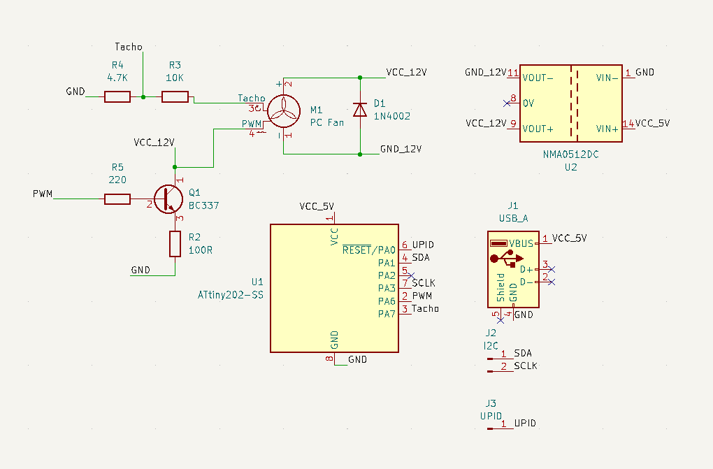
My suggestion was intended for handling any fan motor. The Q1, BC337, is surely good enough for currents within its limit. Just add a serial resistor between the controller pin and the base of the transistor. 220 Ohm will save the output of the controller.
Okey. The tacho is fed from 12 volt. I would like to see a kick back diode between the fan PWM and + terminals, just to be sure. When the transistor is in the switch off state the current induced by the fan motor needs to find a way.
Yes I forgot to add that because I was currently not sure which kind of diode I need and were I should have put that. Do I have to use a Schottky diode? (Some project have diodes some don´t have them. I mostly saw them on DC controlled circuts so far so I am not sure how to do it right)
Can you explain why the current flows back on the PWM pin I tought that Is an Input only pin. Isn´t that connected to the microcontroller which translates the PWM signal to set the speed on the motor.
Or did you mean just between the + and - terminal of the pwm fan?
Do I need the R1 then I just miss matched that resistor it was intended to be the base resistor. Since I do not know that mutch about electronics it would be interessting to know: Does may emitter resistor actually helps my circut (make it more stable) or does it just slow down the circuit?
No the Wire is a lib which helps me to use the attiny as I2C-Slave. The I2C-Slave can be controlled by an I2C-Master which can set the speed of the fan. The I2C-Slave uses the received speed to set the speed of the PWM fan .
At the moment I did not test the code so far, since I need to complet the circuit first. I also would like if it works to get rid of the delay in mesure but first I must see if the code works as intended
Use a common silicon diode. 1N4007 would be fine.
To limit the fault finding, cut the wireless out. Instead of reading the speed from the wireless assign a value to the speed variable. This way the motor handming can be debugged.
I think you got your pins mixed up.
According to datasheet page 14 table 5.1, SDA is indeed on PA1 but SCL is on PA2. Not 100% sure since I haven't used the IC yet but thats how it looks to me, please correct me if I misunderstood something.