ATtiny25 - assembly - BOD disable for sleep mode - error

Mustafa

I really appreciate that you do take time to look at my issue ..
Can you please confirm the following (also to check if I missed something )

  • The chip tiny25 version H have the BOD function implemented .
  • Code seems to be oki ..
  • therefore it is studio not able to build the function .. (is this statement correct?)
    If yes, is there a way to compile the assembly code with another software ? After I can load the .hex in the chip with avrdude .

By the way Mostafa ..
Is there a topic on the forum talking about how to create an attiny low supply voltage alarm (flashing led) ..
Guess the function should be done with the internal voltage reference ..right ?

I tried with ATtiny85, the Assembler does not compile BODS and BODSE; but, the Arduino IDE with ATtinyCore compiles the following line:

MCUCR |= (1 << BODS) | (1 << BODSE);

If you clearly describe the objectives of your ATtiny25 ATtiny85 based project/product, I can try to develop the sketch for you (using Arduin IDE + AttinyCore) and provide you the Intel-hex file which you can upload in your target MCU. You can do the same job by haviing one or both of the following Dev Boards.

Fig-2 comes with an empty socket where you can place Bootloadered-ATtiny85. (ATtiny25 has only 2 Kbyte flash and is no good for the following Dev Boards as the Boot Loader occupies around 2 KByte flash.)

DigisparkAttiny85Board
Figure-1:

image
Figure-2:

Oki .. I will check out to create the hex file with 1rduino ide ..
Once I have it, I can transfert it using stk500 and avr dude in order to save the 2k memory ..
Would like to avoid to install micronucleus just to communicate with usb ..

Will update you asap .. I am done for today .. :blush:
Thanks so much guy for your interest .. really appreciate ..

1 Like

But I would be really interested if you can provide me a piece of code to get a low voltage blinking lzd (port4) alarm ..
Or at least sending me the logical how to do it ..
This would save me jours of investigation..

The assembler has no knowledge of what version your chip is. (I found that same passage in the datasheet. I "assume" that since my datasheet is dated 2010, all tiny25 chips currently around are likely to be newer than that.)

However, that doesn't mean that the tn25def.inc file has been updated :frowning:
(The one I have says it was generated automatically from ATtiny25.xml)

BODS and BODSE are defined in the iotnx5.h file (via iotn25.h), so I have two suggestions:

  • Instead of .include tn25def.inc, try #include <iotn25.h> (or perhaps just io.h)
    AFAIK, current versions of AVRASM support C-style preprocessing as well as the assembler format .inc files.
  • Manually define the constants in your source code, with a nice comment complaining that they're not in the .inc file.
1 Like

Thank you so much for expert opinion.

Guys

It looks like a start of solution :slight_smile:
As i am someone who needs to fully understand what he is doing , I will try both solutions !
therfore, i have questions

1st solution :
Shouldn't it be "#include <iotn25.h> (or perhaps just io.h) " instead of "Instead of .include tn25def.inc, try #include <iotn25.h> (or perhaps just io.h)
AFAIK, current versions of AVRASM support C-style preprocessing as well as the assembler format .inc files.
Think i will still need the tn25def.inc for other functions. --> please confirm

2nd solution
"Manually define the constants in your source code, with a nice comment complaining that they're not in the .inc file"
unfortunatly here i do not have a cluehow to define a constant in the source code. MAybe you can help by providing the code and letting me know where to add it .. from this i can try to understand the meaning of the code ..

By the way .. thanks you very much for your effort.

Hints:
To put HIGH (1) at BODS bit of MCUCR Register, the following codes did not work:

ldi r23, (1 <<BODS)
out MCUCR, r23

We may try the following codes:

in   r23, MCUCR
ori  r23, 0x80
out  MCUCR, r23  ; BODS-bit = bit-7 of MCUCR = HIGH; all other bits are unaffected)

Now, using #define directive (if I have understood post #27 correctly.)

#define  BODS 0x80
in   r23, MCUCR
ori  r23, BODS
out  MCUCR, r23

What are these-- ATtiny85 has only 32 Registers: R0 - R31?

oups .. This is just comments table that I have created at the beguining of my learning process one year ago .. but thanks .; i will correct it .

Mostafa

I tryed your code below and I can compile now .;
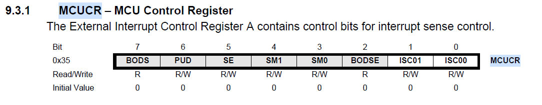
in   r23, MCUCR
ori  r23, 0x80
out  MCUCR, r23  ; BODS-bit = bit-7 of MCUCR = HIGH; all other bits are unaffected)

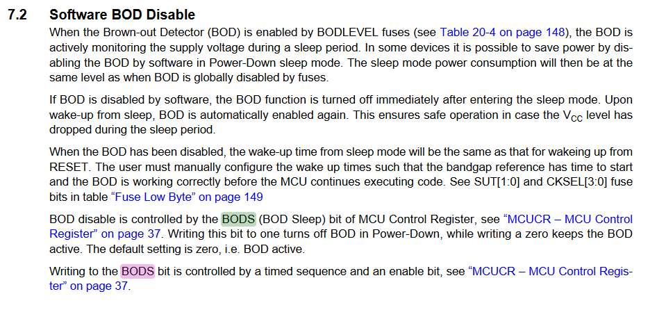
I have no way to check the consumtion of the attiny, I still have a concern if it does work really as we do not have respected the following from the datsheet.

"In order to disable BOD during sleep the BODS bit must be written to logic one. This is controlled by a timed sequence and the enable bit, BODSE in MCUCR.
1 - both BODS and BODSE must be set to one.
2 - within four clock cycles, BODS must be set to one and BODSE must be set to zero
3 - The BODS bit is active three clock cycles after it is set. A sleep instruction must be executed while BODS is active in order to turn off the BOD for the actual sleep mode. The BODS bit is automatically cleared after three clock cycles
"

We have not done the 1 .
We have made the 2 .
I will change the prog to have the SLEEP instruction in the 3 clock cycles .. to respect the 3.
But this is also make me thin that it is recommended to set the SM1 just before the SLEEP instruction.
so what would you think about the lower code ?

;
; test 1.asm
;
; Created: 28/01/2024 
; Author : Tic & Tac
;


; REGISTER USAGE
;               | sbr/cbr            | sbrs/sbrc       | Comment

; R16           |                    |                 |
; R17           |                    |                 |
; R18           |                    |                 |
; R19           |                    |                 |
; R20           |                    |                 |
; R21           |                    |                 |
; R22           |                    |                 |
; R23           |                    |                 |
; R24           |                    |                 |
; R25           |                    |                 |
; R26           |                    |                 |
; R27           |                    |                 |
; R28           |                    |                 |
; R29           |                    |                 |
; R30           |                    |                 |
; R31           |                    |                 |


.include "tn25def.inc"		;Include bibliotheque


;=========================================================================   Interrupt Watchdog- Vector Table - DEBUT  ==========================================================================================================================


		.cseg
		.org	$0000		;External Pin, Power-on Reset, Brown-out Reset, Watchdog system Reset
RESET:	nop
		rjmp	START

		.org	$000D		;WDT Timeout interrupt vector
		reti

		.org	$0010		;application space	

;=========================================================================  Interrupt Watchdog- Vector Table - FIN  ==========================================================================================================================

;=========================================================================  Port Parameter +Value  - DEBUT  ==========================================================================================================================

START:	;init PORTB
		sbi DDRB,PB0							;PB/0 OUT. all others port IN (charge pump entree)
		sbi DDRB,PB1							;PB/1 OUT. all others port IN (Half bridge)
		sbi DDRB,PB2							;PB/2 OUT. all others port IN (Half bridge)
		sbi DDRB,PB3							;PB/3 OUT. all others port IN (charge pump sortie)
		sbi DDRB,PB4							;PB/4 OUT. all others port IN (Light)
		cbi DDRB,PB5							;PB/5 INPUT. 
		
		cbi portb,pb0							; OFF alimentation Charge pump	(verification)
		cbi portb,pb1							; OFF alimentation Charge pump	(verification)
		cbi portb,pb2							; OFF alimentation Charge pump	(verification)
		cbi portb,pb3							; OFF alimentation Charge pump	(verification)
		cbi portb,pb4							; OFF alimentation Charge pump	(verification)
		cbi portb,pb5							; set pulldown input

		ldi R17,0x32							; EEprom Adress Low
		ldi R24,0x04							; pulse lengh setting 
		ldi R26,0x02							; compteur signal court / long (si R26=0 alors long
		ldi R27,0x0a							; ( avant b) Valeur du nombre de relative JUMP dans R25 (19 hexa = 25 decimal)


	;==============================================================================================
	;                                       Start -  flash PB0 - 2 times 
	;==============================================================================================
	
	;loop count down (used as timer)
	sbi PORTB,PB4								; light ON PB4
		ldi R20,0x20
		Tempo_EEPROM_311:
				ldi R19,0xff
				Tempo_EEPROM_031:
				dec R19							; Dec value R -1 
			brne Tempo_EEPROM_031				; Compare Valu and loop till = 0		
		dec R20									; Dec value R -1  
	brne Tempo_EEPROM_311						; Compare Valu and loop till = 0  		
cbi PORTB,PB4									; light OFF PB4

;loop count down (used as timer)
ldi R20,0xff
		Tempo_EEPROM_3111:
				ldi R19,0xff
				Tempo_EEPROM_03111:
				dec R19							; Dec value R -1
			brne Tempo_EEPROM_03111				; Compare Valu and loop till = 0	
		dec R20									; Dec value R -1 
	brne Tempo_EEPROM_3111						; Compare Valu and loop till = 0  		
sbi PORTB,PB4									; light ON PB4

;loop count down (used as timer)
ldi R20,0x20
		Tempo_EEPROM_3113:
				ldi R19,0xff
				Tempo_EEPROM_03112:
				dec R19							; Dec value R -1 
			brne Tempo_EEPROM_03112				; Compare Valu and loop till = 0		
		dec R20									; Decrememnte 1 a R(egistre)20 a chaque passage 
	brne Tempo_EEPROM_3113						; Compare Valeur R(egristre)20 et boucle tant que pas egal a 0   		
cbi PORTB,PB4									; light OFF PB4


	;==============================================================================================
	;                                         Watch dog - setting 
	;==============================================================================================

		out SREG,R15									; load SREG


;init WDT for interrupt mode
		ldi		r23, (1<<WDCE)|(1<<WDE)
		out		WDTCR, r23
		ldi		r23, (1<<WDIE)|(0<<WDE)|(0<<WDP0)|(1<<WDP1)|(0<<WDP2)|(0<<WDP3)	; sec time out WDT interrupt; no system reset
		out		WDTCR, r23
        sei											; global interrupt enable bit is active
	
L1_INTERIEUR:											;init sleep modes
		ldi		r23, (1<<SM1)							;Power-down mode
		out		MCUCR, r23
		in		r23, MCUCR
		ldi		r23, (1<<SE)							;sleep mode enabled
		out		MCUCR, r23							;put MCU into sleep

;init brown out detection desealble for sleep mode
		in   r23, MCUCR
		ori  r23, 0x80
		out  MCUCR, r23									 ; BODS-bit = bit-7 of MCUCR = HIGH; all other bits are unaffected)

L1A_INTERIEUR:	
		in R15,SREG									;save Sreg
		wdr
		sleep											


L2_INTERIEUR:		;wakeup label; flash LED

	
	;==============================================================================================
	;                             Count down Watch Dog - 3 times + light each count down 
	;==============================================================================================

	ldi R27,0x06										; Set value count down 

Loop_watchdog_INTERIEUR:								; count down  6 = 0.64ms * 6 loops 
		dec R27											; Decrememnte 1 a R(egistre)27 a chaque passage 
		
		;loop count down (used as timer)
		sbi PORTB,PB4									; light ON PB4
		ldi R20,0x20
		Tempo_001:
				ldi R19,0xff
				Tempo_002:
				dec R19									; Dec value R -1
			brne Tempo_002								; Compare Valu and loop till = 0 		
		dec R20											; Dec value R -1 
		brne Tempo_001									; Compare Valu and loop till = 0  		
		cbi PORTB,PB4									; light OFF PB4
		
		brne L1A_INTERIEUR			; Compare Valeur R(egristre)27 et boucle tant que pas egal a 0	
		ldi R27,0x0b		; Valeur du nombre de relative JUMP dans R27 (longeur watchdog)


	;==============================================================================================
	;                             Wake up Watch dog - 3 times
	;==============================================================================================


		;loop count down (used as timer)
		sbi PORTB,PB4							; light ON PB4
		ldi R20,0x20
		Tempo_out_001:
				ldi R19,0xff
				Tempo_out_002:
				dec R19							; Dec value R -1
			brne Tempo_out_002					; Compare Valu and loop till = 0 		
		dec R20									; Dec value R -1
		brne Tempo_out_001						; Compare Valu and loop till = 0   		
		cbi PORTB,PB4							; light OFF PB4

		;loop count down (used as timer)
		ldi R20,0xff
		Tempo_out_0011:
				ldi R19,0xff
				Tempo_out_00211:
				dec R19							; Dec value R -1
			brne Tempo_out_00211				; Compare Valu and loop till = 0 		
		dec R20									; Dec value R -1
		brne Tempo_out_0011						; Compare Valu and loop till = 0   		
		sbi PORTB,PB4							; light OFF PB4

		;loop count down (used as timer)
		ldi R20,0x20
		Tempo_out_0013:
				ldi R19,0xff
				Tempo_out_00212:
				dec R19							; Dec value R -1 
			brne Tempo_out_00212				; Compare Valu and loop till = 0 		
		dec R20									; Dec value R -1 
		brne Tempo_out_0013						; Compare Valu and loop till = 0   		
	cbi PORTB,PB4								; light OFF PB4

	;loop count down (used as timer)
	ldi R20,0xff
		Tempo_out_00213:
				ldi R19,0xff
				Tempo_out_00214:
				dec R19							; Dec value R -1 
			brne Tempo_out_00214				; Compare Valu and loop till = 0 		
		dec R20									; Dec value R -1
		brne Tempo_out_00213					; Compare Valu and loop till = 0    		
		sbi PORTB,PB4							; light OFF PB4

	;loop count down (used as timer)
	ldi R20,0x20
		Tempo_out_00314:
				ldi R19,0xff
				Tempo_out_00315:
				dec R19							; Dec value R -1 
			brne Tempo_out_00315				; Compare Valu and loop till = 0 		
		dec R20									; Dec value R -1
	brne Tempo_out_00314						; Compare Valu and loop till = 0    		
	cbi PORTB,PB4								; light OFF PB4


rjmp L1A_INTERIEUR					; jumpG

For consistency with the existing MCUCR definitions, I'd do something like:

#define  BODS 7
#define BODSE 2

(this matches the atmel/microchip provided iotnx5.h, BTW.)

Or, if you want to stick to the pure AVRASM2 syntax:

.equ BODS = 7   ; Brownout detection disable
.equ BODSE = 2  ; Brownout disable enable.

And then to meet the whole 3-cycle thing you could do:

in   r23, MCUCR      ;  Current contents
ori  r23, 1<<BODS    ; BODS set
mov R0, R23          ; Copy with BODS set
ori r23, 1<<BODSE    ;now with BODSE and BODS set
out MCUCR, r23       ; Output with both bits set
out MCUCR,  r0       ; immediately output with just BODS
sleep                ; Within 3 cycles of setting BODS

It's not clear to me whether you can set other bits at the same time you're setting BODS, but it doesn't look like the other bits have timing requirements.

1 Like

thanks so much, I will test it tonight ..

Hello Guys

I do mesure the consomtion now ..

  • 1 - At 8MHz and Fuse BODLEVEL1 not activated :
    in sleep mode: I have 0.01mA
    In wake up mode : I have 4.3mA

  • 2 - At 8MHz with Fuse BODLEVEL1 activated :
    in sleep mode: I have 0.5mA
    In wake up mode : I have 4.3mA

  • 3 - At 8MHz with Fuse BODLEVEL1 activated and your proposed code :
    in sleep mode: I have 0.5mA
    In wake up mode : I have 4.3mA

So it seems the BOD code does not work :frowning:

The code I posted wasn’t meant to be complete.
Could you show us the full code that you’re using for your tests?

sure .. here it is

;
; test 1.asm
;
; Created: 28/01/2024 
; Author : Tic & Tac
;


; REGISTER USAGE
;               | sbr/cbr            | sbrs/sbrc       | Comment

; R16           |                    |                 |
; R17           |                    |                 |
; R18           |                    |                 |
; R19           |                    |                 |
; R20           |                    |                 |
; R21           |                    |                 |
; R22           |                    |                 |
; R23           |                    |                 |
; R24           |                    |                 |
; R25           |                    |                 |
; R26           |                    |                 |
; R27           |                    |                 |
; R28           |                    |                 |
; R29           |                    |                 |
; R30           |                    |                 |
; R31           |                    |                 |


.include "tn25def.inc"		;Include bibliotheque (Modified with .equ BODS = 7   ; Brownout detection disable and .equ BODSE = 2  ; Brownout disable enable.)


;=========================================================================   Interrupt Watchdog- Vector Table - DEBUT  ==========================================================================================================================


		.cseg
		.org	$0000		;External Pin, Power-on Reset, Brown-out Reset, Watchdog system Reset
RESET:	nop
		rjmp	START

		.org	$000D		;WDT Timeout interrupt vector
		reti

		.org	$0010		;application space	

;=========================================================================  Interrupt Watchdog- Vector Table - FIN  ==========================================================================================================================

;=========================================================================  Port Parameter +Value  - DEBUT  ==========================================================================================================================

START:	;init PORTB
		sbi DDRB,PB0							;PB/0 OUT. all others port IN (charge pump entree)
		sbi DDRB,PB1							;PB/1 OUT. all others port IN (Half bridge)
		sbi DDRB,PB2							;PB/2 OUT. all others port IN (Half bridge)
		sbi DDRB,PB3							;PB/3 OUT. all others port IN (charge pump sortie)
		sbi DDRB,PB4							;PB/4 OUT. all others port IN (Light)
		cbi DDRB,PB5							;PB/5 INPUT. 
		
		cbi portb,pb0							
		cbi portb,pb1							
		cbi portb,pb2							
		cbi portb,pb3							
		cbi portb,pb4							
		cbi portb,pb5							

		ldi R17,0x32							; EEprom Adress Low
		ldi R24,0x04							; pulse lengh setting 
		ldi R26,0x02							; compteur signal court / long (si R26=0 alors long
		ldi R27,0x0a							; ( avant b) Valeur du nombre de relative JUMP dans R25 (19 hexa = 25 decimal)


	;==============================================================================================
	;                                       Start -  flash PB0 - 2 times 
	;==============================================================================================
	
;loop count down (used as timer)
	sbi PORTB,PB4								; light ON PB4
		ldi R20,0x20
		Tempo_EEPROM_311:
				ldi R19,0xff
				Tempo_EEPROM_031:
				dec R19							; Dec value R -1 
			brne Tempo_EEPROM_031				; Compare Valu and loop till = 0		
		dec R20									; Dec value R -1  
	brne Tempo_EEPROM_311						; Compare Valu and loop till = 0  		
	cbi PORTB,PB4									; light OFF PB4

;loop count down (used as timer)
	ldi R20,0xff
		Tempo_EEPROM_3111:
				ldi R19,0xff
				Tempo_EEPROM_03111:
				dec R19							; Dec value R -1
			brne Tempo_EEPROM_03111				; Compare Valu and loop till = 0	
		dec R20									; Dec value R -1 
	brne Tempo_EEPROM_3111						; Compare Valu and loop till = 0  		
	sbi PORTB,PB4									; light ON PB4

;loop count down (used as timer)
	ldi R20,0x20
		Tempo_EEPROM_3113:
				ldi R19,0xff
				Tempo_EEPROM_03112:
				dec R19							; Dec value R -1 
			brne Tempo_EEPROM_03112				; Compare Valu and loop till = 0		
		dec R20									; Decrememnte 1 a R(egistre)20 a chaque passage 
	brne Tempo_EEPROM_3113						; Compare Valeur R(egristre)20 et boucle tant que pas egal a 0   		
	cbi PORTB,PB4									; light OFF PB4


	;==============================================================================================
	;                                         Watch dog - setting 
	;==============================================================================================

		out SREG,R15									; load SREG


;init WDT for interrupt mode
		ldi		r23, (1<<WDCE)|(1<<WDE)
		out		WDTCR, r23
		ldi		r23, (1<<WDIE)|(0<<WDE)|(0<<WDP0)|(1<<WDP1)|(0<<WDP2)|(0<<WDP3)	; sec time out WDT interrupt; no system reset
		out		WDTCR, r23
        	sei										; global interrupt enable bit is active
	
L1_INTERIEUR:											;init sleep modes
		ldi		r23, (1<<SM1) | (1<<SE)																;Power-down mode
		out		MCUCR, r23


L1A_INTERIEUR:	
		in R15,SREG									;save Sreg
		wdr
;init brown out detection desealble for sleep mode
		in   r23, MCUCR      ;  Current contents
		ori  r23, 1<<BODS    ; BODS set
		mov R0, R23          ; Copy with BODS set
		ori r23, 1<<BODSE    ;now with BODSE and BODS set
		out MCUCR, r23       ; Output with both bits set
		out MCUCR,  r0       ; immediately output with just BODS
		sleep                ; Within 3 cycles of setting BODS


L2_INTERIEUR:		;wakeup label; flash LED

	
	;==============================================================================================
	;                             Count down Watch Dog - 3 times + light each count down 
	;==============================================================================================

	ldi R27,0x06										; Set value count down 

Loop_watchdog_INTERIEUR:									; count down  6 = 0.64ms * 6 loops 
		
		
;loop count down (used as timer)
		sbi PORTB,PB4									; light ON PB4
		ldi R20,0x20
		Tempo_001:
				ldi R19,0xff
				Tempo_002:
				dec R19									; Dec value R -1
			brne Tempo_002								; Compare Valu and loop till = 0 		
		dec R20											; Dec value R -1 
		brne Tempo_001									; Compare Valu and loop till = 0  		
		cbi PORTB,PB4									; light OFF PB4
		
		dec R27										; Decrememnte 1 a R(egistre)27 a chaque passage 
		brne L1A_INTERIEUR								; Compare Valeur R(egristre)27 et boucle tant que pas egal a 0	
		

	;==============================================================================================
	;                             Wake up Watch dog - 3 times
	;==============================================================================================


		;loop count down (used as timer)
		sbi PORTB,PB4							; light ON PB4
		ldi R20,0x20
		Tempo_out_001:
				ldi R19,0xff
				Tempo_out_002:
				dec R19							; Dec value R -1
			brne Tempo_out_002					; Compare Valu and loop till = 0 		
		dec R20									; Dec value R -1
		brne Tempo_out_001						; Compare Valu and loop till = 0   		
		cbi PORTB,PB4							; light OFF PB4

		;loop count down (used as timer)
		ldi R20,0xff
		Tempo_out_0011:
				ldi R19,0xff
				Tempo_out_00211:
				dec R19							; Dec value R -1
			brne Tempo_out_00211				; Compare Valu and loop till = 0 		
		dec R20									; Dec value R -1
		brne Tempo_out_0011						; Compare Valu and loop till = 0   		
		sbi PORTB,PB4							; light OFF PB4

		;loop count down (used as timer)
		ldi R20,0x20
		Tempo_out_0013:
				ldi R19,0xff
				Tempo_out_00212:
				dec R19							; Dec value R -1 
			brne Tempo_out_00212				; Compare Valu and loop till = 0 		
		dec R20									; Dec value R -1 
		brne Tempo_out_0013						; Compare Valu and loop till = 0   		
	cbi PORTB,PB4								; light OFF PB4

	;loop count down (used as timer)
	ldi R20,0xff
		Tempo_out_00213:
				ldi R19,0xff
				Tempo_out_00214:
				dec R19							; Dec value R -1 
			brne Tempo_out_00214				; Compare Valu and loop till = 0 		
		dec R20									; Dec value R -1
		brne Tempo_out_00213					; Compare Valu and loop till = 0    		
		sbi PORTB,PB4							; light OFF PB4

	;loop count down (used as timer)
	ldi R20,0x20
		Tempo_out_00314:
				ldi R19,0xff
				Tempo_out_00315:
				dec R19							; Dec value R -1 
			brne Tempo_out_00315				; Compare Valu and loop till = 0 		
		dec R20									; Dec value R -1
	brne Tempo_out_00314						; Compare Valu and loop till = 0    		
	cbi PORTB,PB4								; light OFF PB4


rjmp L1A_INTERIEUR					; jumpG

@westfw
@online67
I am presenting below my investigation on the power consumption of ATtiny85 in power-down sleep mode. I have used the follwoing Digispark ATtiny Dev Board (Fig-1).
DigisparkAttiny85Board
Figure-1:

Schematic of Fig-1:


Figure-2:

I have removed the "Power Indicator LED - D1" of Fig-2 and have kept LED-D2 to visualize wake-up event (pls, see the sketch).

I have uploaded the following sketch into 16-MHz ATtiny85 of Digispark Board using Arduino IDE.

#include<avr/sleep.h>
#include<avr/wdt.h>
#define LED 1

void setup()
{
  //Serial.begin(9600);
  pinMode(LED, OUTPUT);
  digitalWrite(LED, LOW);
  //Serial.println("System Reset/Boot");

  MCUCR |= (1 << SM1);  //power down mode
  //-------------------------------
  noInterrupts(); //ensure no interruptwhile initializing WDTCSR Reg
  wdt_reset();
  WDTCR |= (1 << WDCE) | (1 << WDE);//both bits must be HIGH
  //above bits will assume LOW with next 4-cycles
  //so keep new value for WDTCSR by the following line in uffer
  //after 4 cycles, the new value is loaded from Buffer to WDTCSR
  WDTCR = (1 << WDIE) | (0 << WDE)
           | (1 << WDP3)|(1<<WDP0); //WDT inerrupt Mode time-out 8 sec
  interrupts();
  //------------------------------------
}

void loop()
{
  bitSet(MCUCR, SE);  //Sleep enable
  sleep_cpu();  //asm: sleep; the MCU sleeps for 8-sec
  //L1: Serial.println("Wake up MCU.");
  bitClear(MCUCR, SE);  //after wake-up, programexecution begins here

  for (int i = 0; i < 5; i++)
  {
    digitalWrite(LED, HIGH);
    delay(100);
    digitalWrite(LED, LOW);
    delay(100);
  }
}

ISR(WDT_vect)
{
  //Serial.print("WDT interrupt has occured to ");
}

After sketch uploading, I have disconnected the Digispark Board from PC. I have applied 5V power on the board via 5V-pin (J2 connector, Fig-2) with a DVM (200 mA scale) in series at the live side. During sleep mode, my DVM shows: 5.4 mA. After wake-up, DVM shows 20.5 mA while blinking LED-D2.

Now, I am investigating the BOD case.
The data sheets say that the BODS and BODSE bits are read-only (Fig-3). So, what can be done to investigate the BOD-disable feature?


Figure-3:

Agree but the datasheet is also saying :


and the below limitations :

1 Like