Hi !
For a project I need to use the dc motor FIT0450 which is equiped of an encoder to make rotate of a certain angle and stop.
I also use the motor drive L293d.
But the main problem comes from the attiny84 (A-PU), I can't achieve to make it work surrely due to the interrupt on the pins.
Here my code :
#include <avr/io.h>
#include <avr/interrupt.h>

// --- Broches de l'encodeur et du moteur ---
// Pour cet exemple, nous utilisons le mapping suivant :
// ENCODER_A -> Pin 4 (correspond à PCINT4)
// ENCODER_B -> Pin 5
#define ENCODER_A 4     // PCINT4
#define ENCODER_B 5

#define IN1 2           // Direction +
#define IN2 3           // Direction -
#define ENA 8           // PWM vitesse

// --- Variables globales ---
volatile long encoderCount = 0;

// --- Paramètres PID ---
float Kp = 1.5;
float Ki = 0.02;
float Kd = 0.1;

float error = 0, lastError = 0;
float integral = 0, derivative = 0;
float output = 0;

long targetPosition = 0;      // Position à maintenir
int margin = 5;               // Marge de tolérance

// --- Variables pour la non-blocage ---
unsigned long previousTime = 0;
const unsigned long sampleTime = 10;  // Temps d'échantillonnage en ms

void setup() {
  // Configuration des broches pour l'encodeur
  pinMode(ENCODER_A, INPUT);
  pinMode(ENCODER_B, INPUT);

  // Configuration des broches du moteur
  pinMode(IN1, OUTPUT);
  pinMode(IN2, OUTPUT);
  pinMode(ENA, OUTPUT);

  // Activation de l'interruption sur changement d'état pour ENCODER_A :
  // Utilisation de PCMSK1 et GIMSK pour le port A sur ATtiny84.
  // PA4 correspond à PCINT12.
  PCMSK1 |= (1 << PCINT4);   // Activer l'interruption sur PCINT12
  GIMSK |= (1 << PCIE1);       // Activer les interruptions du port A

  // Autorisation des interruptions globales
  sei();
}

// --- Boucle principale (non bloquante) ---
void loop() {
  unsigned long currentTime = millis();
  if (currentTime - previousTime >= sampleTime) {
    previousTime = currentTime;
    controlLoop();
  }
}

// --- Fonction principale de contrôle PID ---
void controlLoop() {
  long currentPosition;
  // Lecture de la position actuelle de l'encodeur de manière atomique
  noInterrupts();
  currentPosition = encoderCount;
  interrupts();

  error = targetPosition - currentPosition;

  if (abs(error) <= margin) {
    stopMotor();
    integral = 0;  // Réinitialiser l'accumulation
    output = 0;
  } else {
    integral += error;
    derivative = error - lastError;
    lastError = error;

    output = Kp * error + Ki * integral + Kd * derivative;
    output = constrain(output, -255, 255);

    if (output > 0) {
      digitalWrite(IN1, HIGH);
      digitalWrite(IN2, LOW);
      analogWrite(ENA, (int)output);
    } else {
      digitalWrite(IN1, LOW);
      digitalWrite(IN2, HIGH);
      analogWrite(ENA, (int)(-output));
    }
  }
}

// --- Arrêt du moteur ---
void stopMotor() {
  digitalWrite(IN1, LOW);
  digitalWrite(IN2, LOW);
  analogWrite(ENA, 0);
}

// --- ISR pour le changement d'état sur PCINT[7:0] ---
// Ici, on utilise le vecteur PCINT_vect, qui gère les broches 0 à 7 (dont notre PCINT4)
ISR(PCINT_vect) {
  updateEncoder();
}

// --- Mise à jour de la position de l'encodeur ---
void updateEncoder() {
  // Lecture des broches de l'encodeur
  bool A = digitalRead(ENCODER_A);
  bool B = digitalRead(ENCODER_B);

  // Méthode simple de décodage quadrature :
  // Si les lectures A et B sont identiques, incrémentation, sinon décrémentation.
  if (A == B) {
    encoderCount++;
  } else {
    encoderCount--;
  }
}
I would prefer to not change the pins if possible (i'm using pcbs that are already made).
You must explain more clearly. What did you want or expect to happen? What happens in reality? Be clear about the differences. What do you mean by "surrely"?
The motor is initialy at the position 0 and when it is moved the encoder change the change the current position and the motor should automatically come back to the 0 position.
The motor is spinning endlessly or not at all...
I think the problem come from the interrupts on the encoder pins that not detect the changes on these.
Even with the pullup, the problem remain.
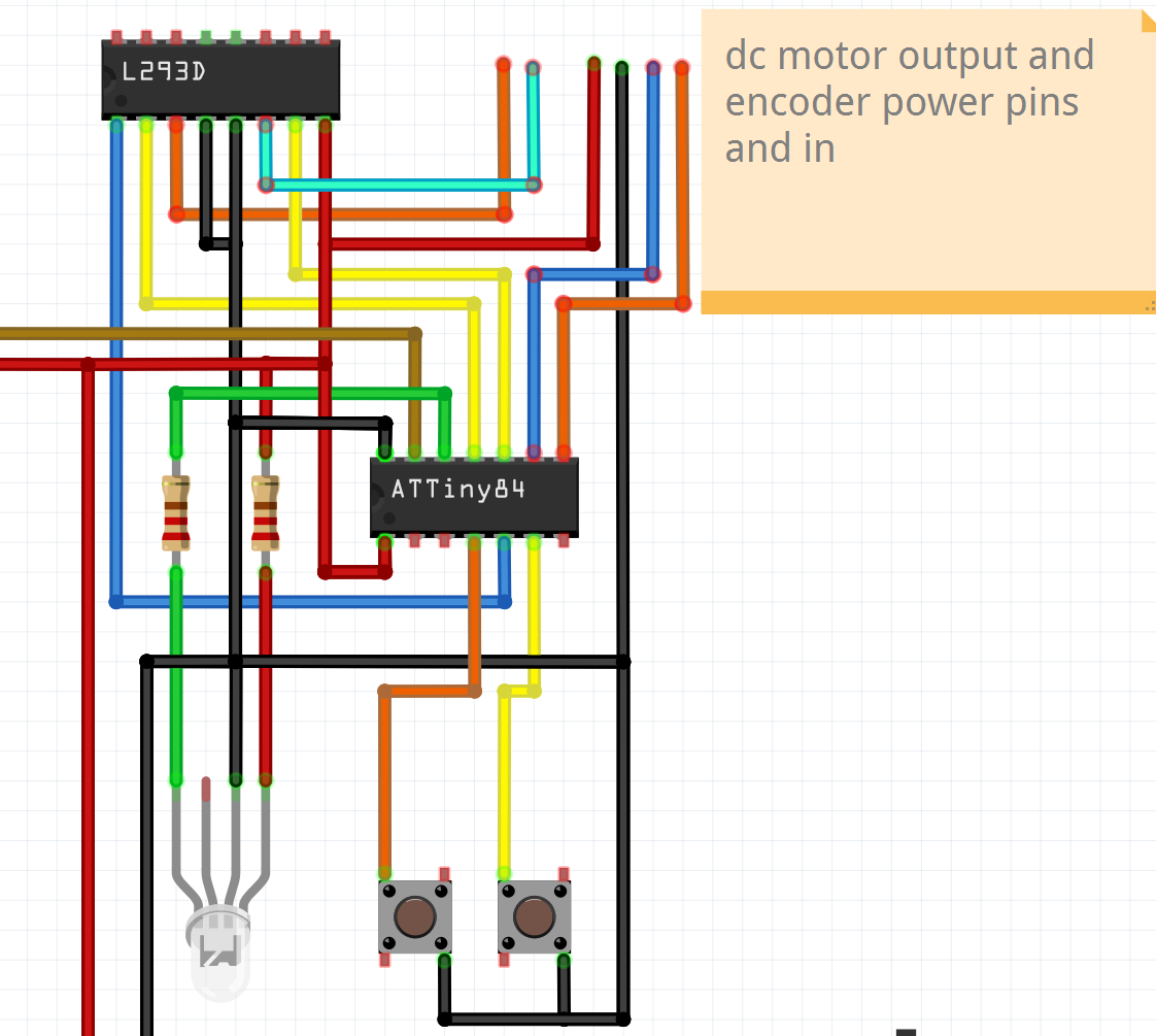
Posting an annotated schematic showing how everything is connected will help us answer your questions. Be sure to show all connections, power, ground, power sources etc. Also post links to the technical information on the devices.
I first tested the program on uno and it works! But when i switched to the at, the attachpintointerrups which was use on uno does not exist on it so i had to make it a different way.... and i think that this thing that doesn't work.
The motor should automatically go back to the zero pos zhen i turn it manually but it doesn't.
How will you instruct the motor to return to the zero position? The motor has no intelligence. The encoder doesn't even know what the zero position is.
To get your program to give such control, it must remember how many steps the encoder has done since the zero position, and then to return to that position you need code to move the motor to that encoder position. Have you programmed to do all that?
Okay I understood, yes the motor does all this step, the encoder send informations to the microship about his rotation (in the variable encoderCount ) and when this variable is out of the range of the error then, the at84 switch on one of the pin that control the direction of the motor and also use the pwm pin to control speed.
So yes it does all the steps to make the motor rotate as i want to.
I tried ! and it works :
#include <Arduino.h>

// --- Broches de l'encodeur et du moteur ---
#define ENCODER_A 2     // INT0
#define ENCODER_B 3     // Interruptions externes disponibles sur Uno

#define IN1 4           // Direction +
#define IN2 5           // Direction -
#define ENA 9           // PWM vitesse

// --- Variables globales ---
volatile long encoderCount = 0;

// --- Paramètres PID ---
float Kp = 1.5;
float Ki = 0.02;
float Kd = 0.1;

float error = 0, lastError = 0;
float integral = 0, derivative = 0;
float output = 0;

long targetPosition = 500;      // Position à maintenir
int margin = 5;                 // Marge de tolérance

// --- Variables pour la non-blocage ---
unsigned long previousTime = 0;
const unsigned long sampleTime = 10;  // Temps d'échantillonnage en ms

void setup() {
  // Configuration des broches pour l'encodeur
  pinMode(ENCODER_A, INPUT_PULLUP);
  pinMode(ENCODER_B, INPUT_PULLUP);

  // Configuration des broches du moteur
  pinMode(IN1, OUTPUT);
  pinMode(IN2, OUTPUT);
  pinMode(ENA, OUTPUT);

  // Activation des interruptions externes
  attachInterrupt(digitalPinToInterrupt(ENCODER_A), updateEncoder, CHANGE);

// --- Boucle principale (non bloquante) ---
void loop() {
  unsigned long currentTime = millis();
  if (currentTime - previousTime >= sampleTime) {
    previousTime = currentTime;
    controlLoop();
  }
}

// --- Fonction principale de contrôle PID ---
void controlLoop() {
  long currentPosition;
  // Lecture de la position actuelle de l'encodeur de manière atomique
  noInterrupts();
  currentPosition = encoderCount;
  interrupts();

  error = targetPosition - currentPosition;

  if (abs(error) <= margin) {
    stopMotor();
    integral = 0;  // Réinitialiser l'accumulation
    output = 0;
  } else {
    integral += error;
    derivative = error - lastError;
    lastError = error;

    output = Kp * error + Ki * integral + Kd * derivative;
    output = constrain(output, -255, 255);

    if (output > 0) {
      digitalWrite(IN1, HIGH);
      digitalWrite(IN2, LOW);
      analogWrite(ENA, (int)output);
    } else {
      digitalWrite(IN1, LOW);
      digitalWrite(IN2, HIGH);
      analogWrite(ENA, (int)(-output));
    }
  }
}

// --- Arrêt du moteur ---
void stopMotor() {
  digitalWrite(IN1, LOW);
  digitalWrite(IN2, LOW);
  analogWrite(ENA, 0);
}

// --- Mise à jour de la position de l'encodeur ---
void updateEncoder() {
  bool A = digitalRead(ENCODER_A);
  bool B = digitalRead(ENCODER_B);

  if (A == B) {
    encoderCount++;
  } else {
    encoderCount--;
  }
}
But in fact it's when i ported to the attiny, I had to change the attachInterrupt(digitalPinToInterrupt(ENCODER_A), updateEncoder, CHANGE);
because it doesn't exist on the at.... after the changes (code on the top of the topic) it doesn't work anymore....
PCMSK1 |= (1 << PCINT4);   // Activer l'interruption sur PCINT12
  GIMSK |= (1 << PCIE1);       // Activer les interruptions du port A

  // Autorisation des interruptions globales
  sei();
The ATTINY84 has two ports so the name should contain an indication of the port.
If the correct vector is not defined to match the interrupt then the program will crash and restart as soon as an interrupt is triggered. Flash a led in setup() to see a crash or add a delay().
Ensure these all match the chosen port/pin:
Which Arduino core are you using for the ATTINY84 ?