I would like to build a simple solar charger circuit for a 6V lead acid battery. I mean realy simple as the charger should just cut off the solar cells from the battery when a certain voltage level is reached.
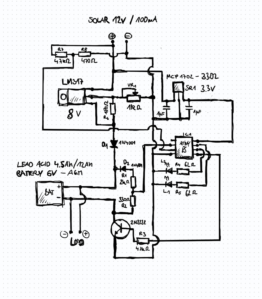
The ATTiny measures the battery voltage via the voltage divider R1+R2 and switches the
2N2222 on through R3 when the voltage level drops below 6.3V (I measured the fully charged 6V battery at 6.4V) and cuts off power at 6.4V. The LM317 provides 7.9V, the voltage drops across D1 by 0.7V so the battery will be charged at 7.2V.
LEDs L1 and L2 will monitor the charging status. Green fully charged, red charging.
The Tiny will be powerd by MCP1702-5002 LDO.
Resistor R6 should limit charging current but Im unsure if this is even necessary since the solar panels (2x6V, 100mA) Im using only provide 100mA.
Im unsure about the diode D2: I want to avoid that the battery looses power to the voltage divider R1+R2. Is this one placed correctly?
How big is that 6volt battery, and what type (flooded, AGM).
You might not need any regulation if the solar cell is <5% of the Ahr ratiing of the battery.
If you want to limit end of charge voltage, then a shunt regulator could be a better option.
Leo..
You should keep charging the battery until it reaches 7v i'd say. A lead acid battery will approximately be 6.4v when fully charged, but not nearly full when reaching 6.4v while charging.
Yes, but the LM317 is rather inefficient. Also you have not taken the voltage drop of the 2n2222 into account.
(and there does not seem to be any purpose for the 1N4001), but the charging voltage is good.
yep i also think there is no real need for it.
Like this your circuit won't work at all. It should be placed between the + of the battery and the voltage divider with te cathode towards the battery, and you will need to take the voltage drop into account. You culd also use an op-amp instead, powered by the ATtiny power to measure the voltage from the battery, You are after all only considering to charge when there is power for the ATtiny.
Then there is the possibility of the current draw for charging the battery, cause the attiny to drop out, but that is a different matter.
Do you have to run the aTTiny at 5volt.
A single solar cell (or two in parallel) charging a 3.3volt LiFePo4 battery that directly powers the chip seems a better option.
Leo..
Exactly, I'm not a user of the ATtiny85, but can you run it with the 32kHz clock crystal, this would make it super low current if it is like the other bigger AT microcontrollers.
The lower speed would still be fast enough for this application.
That's why I mentioned the LiFePo4 battery, which stays close to 3.3volt for much of it's discharge cycle. I charge a 1Ah LiFePo4 with a small solar panel to 3.6volt. It serves as a 20mA night light for up to 12 hours every night. It has a TL431 shunt regulator, set to 3.6volt.
Leo..
First of all: thanks for all your replies and thoughts!
I have two 6V batteries that I would like to charge: one 4.5Ah and one 12Ah both are of type AGM for 2 different projects (It would be nice to use the same solar charger circuit).
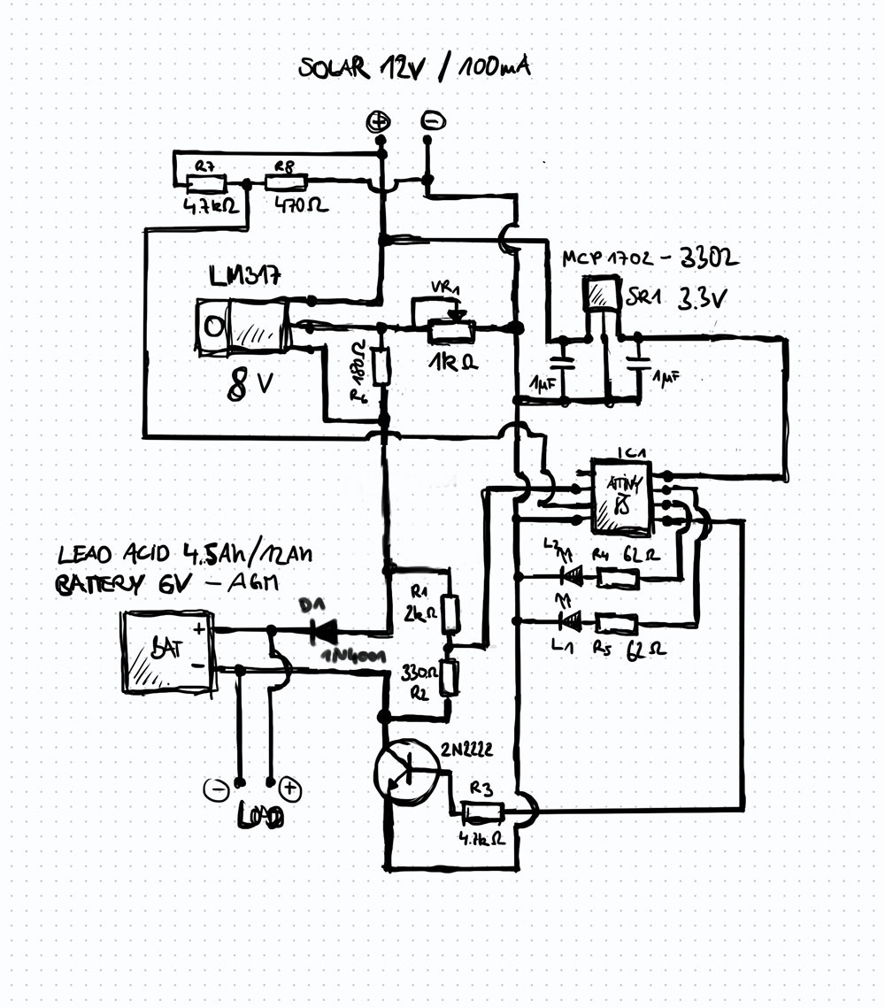
I will change the charging cut-off voltage to 7V!
I will remove the resistor R6 then! I also suspected that this one is even necessary.
This is going to be done!
No, it does not need to be 5V. 3.3V should be also in spec of the ATTiny. There is also a 3.3V LDO available MCP1702-3302 I will change that. In the end the system should not charge the battery for the tiny. The cicuit charges the lead acid battery for a garden monitoring system with a small
waterpump etc. so I want a little more amps and voltage.
The small panels are out of my junk box so I dont know the exact specs unfortunately.
I would run the ATTiny85 with 1MHz internal oscilator! So it would be low power hopefully
I will update the schematic later.
Thanks again for all your very helpfull input!
Hi, @asuryan
Thankyou for the schematic in your first post, it helps a lot in giving advice.
I have redrawn it, hopefully to show the power flow easier and added pin labels.
Increased LM317 voltage to 8V since the voltage drop of 0.7V of D1 + 2N2222 drop of 0.1V (found this value somewhere in another forum!? Hope this is right)
Moved D2 to the voltage divider section, cathode facing towards battery (+)
Changed the voltage divider resistors to analog internal reference of 1.1v
What do you think? A little better?
Thank you very much! I just drawn my changes into my hand drawing as this was easier for the moment but your schematic is way better! What kind of software did you use?
It is still not in the correct spot. In fact there is no need for 2 diodes. just put 1 with the cathode to the junction of the + of the battery and the + of the load, and the anode to the junction of the voltage divider and the Vout of the LM317.
The way you have it now, no current can flow through the voltage divider. Basically what you want is to prevent current flowing from the battery + terminal back into the circuit (both the voltage divider & LM317)
Good point !, well you can only measure the voltage during charging, which is of course all you want to do, since that is the only time the ATtiny is powered. You will need to take the voltage drop of the diode into account.
Yes i'd say so. you should confirm with a voltage meter but that makes sense. Of course the moment you do that, the transistor will disconnect the voltage divider from GND, which will result in an undivided volt reading, which will probably damage your ATtiny. I think maybe the voltage divider should be connected to GND directly, rather than at the junction of the transistor. Hmm, does that disturb things, yeah maybe a little.
I was considering switching the transistor to a PNP, but regardless you can not measure the voltage of the battery unless you are charging it simply because you don't want the voltage divider to drain the battery. I would use an OP-amp to measure the voltage, to solve the whole issue. The op-amp can be powered through the MCP 1702, and does not drain the battery. In fact you can set it up in such a way that you set the threshold for both HIGH and LOW voltage and act according to the results from it.