I'm displaying the supply voltage of arduino UNO on a OLED screen. The UNO code is perectly working.
When I transfer this code to ATTINY85 the voltage readings are incorrect. How to show the correct voltage? (I transfered the code via burning a bootloader & program via an UNO ICSP)
int getVCC() {
   return min(11264/analogRead(12),99);
}
voltage = getVCC();

	oled.drawChar(100,0,voltage/10+'0');
        oled.drawChar(106,0,'.');
        oled.drawChar(112,0,voltage%10+'0');
        oled.drawChar(118,0,'V');
Please show the full sketch and a schematic of the circuit in which the ATTiny85 is supposed to do its analog sampling.
This will answer several questions we may have, for instance how you're running the OLED from a uC that has no hardware I2C support (supposedly you're using some kind of soft-wire approach here?), but also how the analog input is wired (and from what kind of signal source) and what happens in the initial part of your sketch where everything is being set up.
In short: if you give complete information, you may get useful responses. Based on the little snippet you gave so far, I wouldn't know where to start.
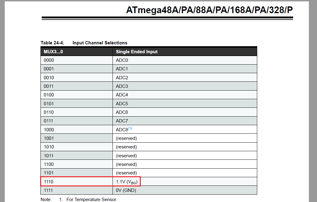
Please explain a little more. The internal 1.1V reference is fixed. You can't calculate anything about it; it's there and cannot be changed. You cannot measure the 1.1V internal reference, let alone use it to calculate Vcc.
I see no pin on the ATTiny85 that would read any analog signal.
I'm not sure what you're trying to do. If you are trying to measure Vcc, then you'll need a voltage divider to bring Vcc to below 1.1V and then measure that value with the 1.1V reference. You can then calculate Vcc in your code. Note that the ATTiny85 does not seem to have a Vcc input to its ADC input MUX as shown in the block diagram on page 123 of the datasheet.
So please explain a bit more what you're actually trying to measure.
However, in standard Uno analogRead should not support this value.
(Take a constant and AND to limit to the pin number.)
But I think it was available in ATtinyCore.
Ok, but it won't say anything about Vcc. The only useful information measuring the internal reference would give is for calibration purposes. This doesn't seem to be what OP is trying to do (although I'm not yet sure what he IS traying to do...)
I don't think you can.
I'd do it the way I proposed: voltage divider on Vcc, then measure it using an ADC pin. So with an external connection to the uC.
No, he just pointed out you can measure the internal 1.1V reference. That's not what you're trying to do. The table @chrisknightley posted shows very clear that the ATTiny85 cannot do what you're trying to do with it. It physically can't measure Vcc without an external connection.
If VCC fluctuates, you can calculate VCC back by measuring 1.1V with reference to VCC.
It is quite used as a means of measuring VCC without using any pins.
(In many cases, the individual difference of 1.1V is measured first, and the magic number is hard-coded.)
You'd still have to measure Vcc, since the internal reference is supposed to be quite stable even if Vcc fluctuates. To measure Vcc, the ADC will need an input from it. The ATTiny85 as you've shown doesn't have this connection internally, so it needs to be made externally. Since Vcc is higher than Vref, there will also need to be a voltage divider.
Ok, then show how you've set up your ADC in your sketch. Which you still haven't posted, so I cannot see to what extent your sketch matches how the 'rest of the world' does it successfully.