Hello,
I need a more accurate thermostat than a mechanical thermostat of the bimetallic type, so I searched for the LM35 and the DS18B20. At first the LM35 seems to be more susceptible to noise, and also has the issue of converting from analog to digital, voltage reference etc.
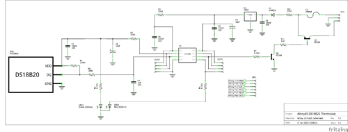
So I opted for the DS18B20, in conjunction with a small low-pass filter to help attenuate noise in the data line.
(Ref.: https://dutta.csc.ncsu.edu/iot_spring17/wrap/1-Wire-Design%20Guide%20v1.0.pdf pg. 63)
As the thermostat needs to operate internally on a switched power supply, up to 50A, and it ends up generating a lot of noise, I activated the WDT, and since I already had some WDT failure experiences with PIC, I would like to know if anyone has had some problem with WDT in ATtiny85, and if you have any tips on that or maybe something else.
I found some texts, like the following: Great Watchdog Timers For Embedded Systems, by Jack Ganssle
I'm using this code (Attached, I was unable to add to the post due to the 9000 character limit):
ATtiny85_DS18B20_Thermostat
And I'm using this hardware:
I did some preliminary testing and so far it has worked well. I need to protect some MOSFET's with a heatsink temperature of up to 115ºC. Eventually the forced ventilation that keeps the heatsink up to 100ºC during normal operation, fails, or the environment is very hot, and then without the protection the MOSFET goes into a short circuit.
Thank you.
Attiny85_DS18B20_thermostat.ino (7.06 KB)


