Hello,
I have written below code to output 500KHz square wave on PB4 pin. I am getting the waveform generated at right frequency but the peak to peak voltage is only 1.24V. I would like it to be at 5V.
Strangely, when I also set PB3 as an output pin, the peak to peak output on PB4 is coming at 5V.
I would not like to set PB3 as output as I need that pin configured as input for some more logic I will add later.
Hence would someone let me know how to get 5V output at PB4 without needing to have PB3 also as output?
I have COM1B1 set and COM1B0 cleared to have PB3 (~OC1B) not connected to the timer1. So not sure why setting this as output is having effect on output voltage of PB4. Even if I make PB3 as output, I don't get any waveform on PB3 (as expected).
How do you know it is 1.24V PTP? How are you measuring that? Multimeter? Oscilloscope? What model of 'scope? Perhaps it is 5V PTP but your equipment is unable to measure it accurately?
Very good point. The first thing I did after reading your reply was to measure the average DC Voltage at PB4 (with PB4 set as output) using a DMM (model Uni-T UT33A+), and indeed, it says 2.5V (the square wave has 50% duty cycle). So according to this, Peak to Peak must be 5V.
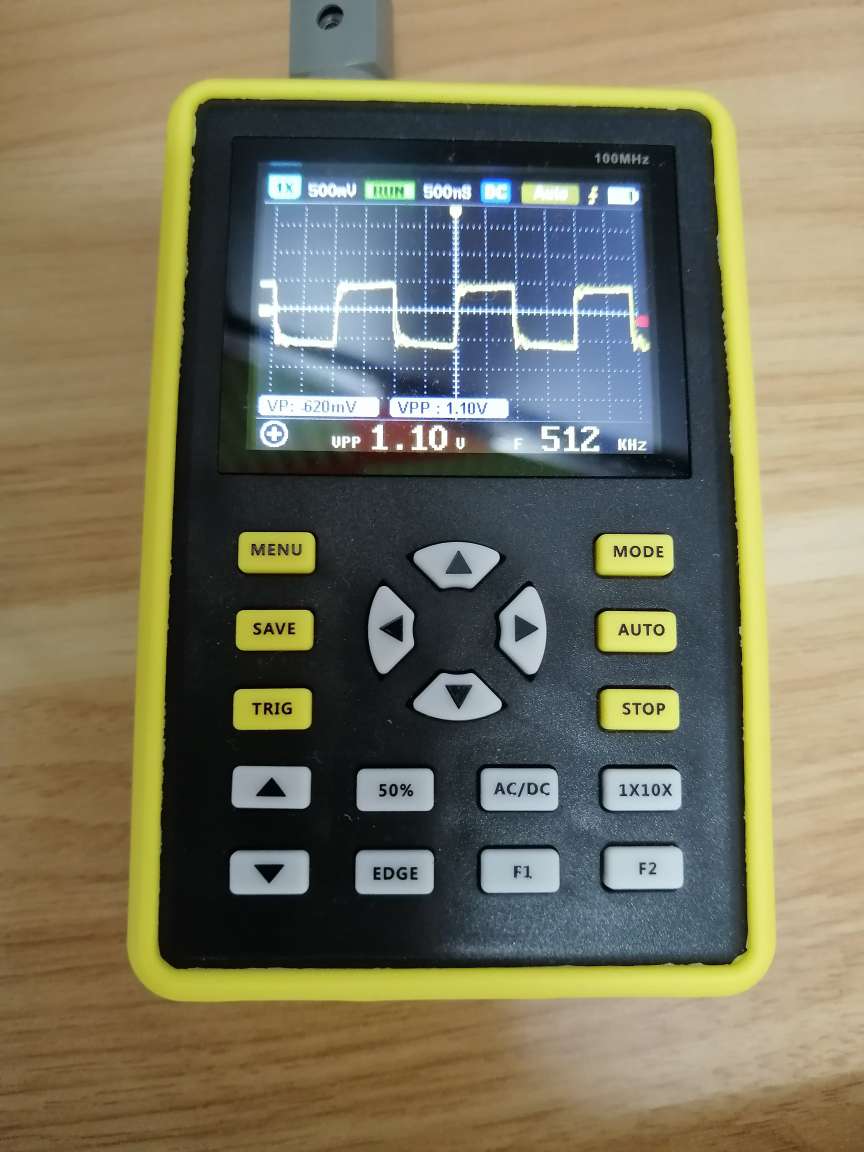
Then I again looked at my Oscope (yeapook handheld Oscilloscope 5012h .. literally got it from here).
Hello @PaulRB ,
I tried various different prescalar settings and brought it down from 500KHz to about 5 KHz. The Oscope VPP (peak to peak voltage) remained at 1.2V . DMM's average voltage always showed 2.5V (not sure if there is a DC offset).
Though, the waveform on Oscope becomes very jittery beyond 50KHz. Not sure, this is how ATTiny85 behaves (since this is PWM mode after all, where we don't expect square waves with sharp edges.. so long as the average voltage is right, it will do).
Maybe, I will harass a colleague of mine and try to get ahold of Siglent or Rigol scope and see how it fares (this is a personal project, doing it in my garage). Any other ideas?
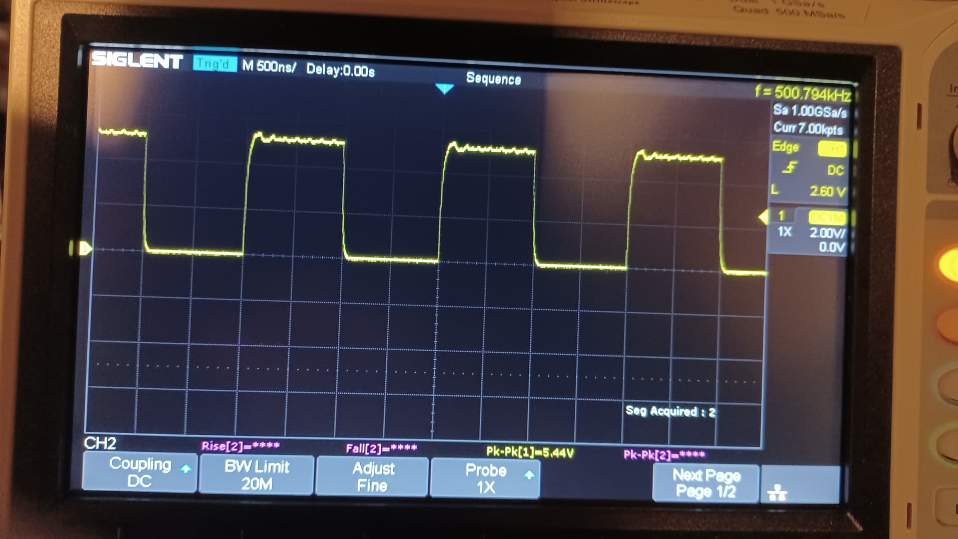
Well I spent some time going over the data sheet and the code and it seems it should work. So.. I got out an Attiny85, my programmer (a bit of a problem since I haven't done this in a while) and a scope. Here is the result...
Hello @oldcurmudgeon ,
You are absolutely right.
I rewired everything again. Now, it works with the same code in post #1. My Oscope shows 5V on PB4 at 500KHz.
Loads of thanks to you and to everyone else for helping to find resolution.
Marking your post as solution.
But what is that solution? Other forum members with a similar problem may find this topic and be frustrated that the original cause of the problem has not been positively identified. @oldcurmudgeon demonstrated, using the same circuit & code but a different 'scope, that it does give 5V PTP signal, but not why your readings were different. Was @Paul_KD7HB 's suggestion the real solution, in fact?
Hello @PaulRB,
I changed my breadboard. I think there is some issue with the breadboard. I had previously only thought of changing components and wires, but after @oldcurmudgeon confirmed that code worked, I started from scratch. Changed all components, wires and breadboard. It worked. Then after few repeats, narrowed down the cause to be the breadboard.More specifically, the area on the breadboard where the ATTiny85 chip was placed. I had used this breadboard off and on only for testing leds, so didn't realize that some specific connection holes were not working ok.
What was happening was that the area where I had put the ATTiny85 was causing some weird coupling between ATTiny85 pins. It didn't damage the chip but the output on PB4 was not coming out right. And since I was using this board as programmer, I had marked the point where I put the ATTiny85 chip, so as to not have to change wiring when flipping different ATTiny85 chips for programming. So even other ATiny85 chips were giving the same issue. Really, Murphy's law in full glory.
Regarding @Paul_KD7HB 's suggestion, I appreciate the reply. Perhaps the photo in post #5 is bit blurry, but near top middle, its showing DC (in little blue square background). So, the scope was in DC mode.
Hello @PaulRB,
I was talking of pattern analyzer style digital output with sharp, 90 degree transition edges, absolutely 0 ringing. I think the ringing and jitter/noise I was seeing was a result of aforesaid coupling due to bad breadboard. As mentioned in post #14, since location of all different ATTiny85 chips was the same, I was suspecting that something was wrong either with code or that ATTiny chips behave this way. I don't see any issues now that breadboard has been changed. I do still see a little bit of ringing around waveform transition edges, but that is acceptable due to possibly issues in scope's waveform capture (like probes inducing stray inductance or capacitence, impedence matching etc.) as well as output pin driving characteristics of the chip.
Yes, I suppose so, at frequencies approaching a megahertz, you are approaching the limits of breadboarding, even with good quality/condition breadboards. Plus, the probes that come with cheap 'scopes are going to be cheap probes...