I am making an automatic school bell which will ring at certain times without the need of human input. However i am experiencing some problems which i have tried to solve myself tho sadly i have failed.
The problem i am experiencing currently is that the rtc doesn't connect with local time and the LCD while ligthing up doesn't show any changes
I am using this youtube video as a refence to help me
https://youtu.be/IXZoSdbT4Dw?si=Buo0EKpN55FgWPyW
This is the code they had given me
#include (Wire.h) //instead of parenthesis () put angle bracket as YouTube description does not allow angle bracket
#include (LiquidCrystal_I2C.h)
#include (DS1302.h)
// Set the LCD address to 0x27 for a 16 chars and 2 line display
LiquidCrystal_I2C lcd(0x3F, 16, 2);

int Hour;
int Min;
int Sec;
int period;
int in1 = 8;
int in2 = 9;
int activate=0;
Time t;

// Init the DS1302
DS1302 rtc(2, 3, 4);

void setup()
{
pinMode(8, OUTPUT);
pinMode(9, OUTPUT);
// Set the clock to run-mode, and disable the write protection
rtc.halt(false);
rtc.writeProtect(false);

// Setup LCD to 16x2 characters
lcd.begin();
Serial.begin(9600);

// The following lines can be commented out to use the values already stored in the DS1302
// rtc.setDOW(SUNDAY); // Set Day-of-Week to FRIDAY
// rtc.setTime(10, 30, 30); // Set the time to 12:00:00 (24hr format)
// rtc.setDate(23, 03, 2020); // Set the date to August 6th, 2010

}

void loop()
{
// Display time on the right conrner upper line

lcd.setCursor(0, 0);
lcd.print("Time: ");
lcd.setCursor(6, 0);
lcd.print(rtc.getTimeStr());
t = rtc.getTime();
Hour = t.hour;
Min = t.min;
Sec = t.sec;

//Display Period Number
lcd.setCursor(0, 1);
lcd.print("Period No: ");
lcd.setCursor(11, 1);
lcd.print(period);

//Period timing, when bell will ring, you can add more period if you want
if ((Hour== 7 && Min== 0 && Sec(= 5)||(Hour== 7 && Min== 30 && Sec(= 5)||(Hour== 8 && Min== 0 && Sec(= 5)||(Hour== 8 && Min== 30 && Sec(= 5)||(Hour== 9 && Min== 30 && Sec(= 5)||(Hour== 10 && Min== 0 && Sec(= 5)||(Hour== 10 && Min== 30 && Sec(= 5)||(Hour== 11 && Min== 0 && Sec(= 5)) {
digitalWrite(in1, HIGH);
digitalWrite(in2, LOW);

Serial.println("motor is running");
if (activate == 0){
period = period +1;
activate =1;
}
}
else if (Hour== 9 && Min== 0 && Sec(= 7) { // Recess break time (Long ring bell)
digitalWrite(in1, HIGH);
digitalWrite(in2, LOW);
lcd.setCursor(11, 1);
lcd.print("Break");
delay(500);
lcd.clear();
}
else if (Hour== 11 && Min== 30 && Sec(= 7) { // School time over (Long Ring bell)
digitalWrite(in1, HIGH);
digitalWrite(in2, LOW);
lcd.setCursor(11, 1);
lcd.print("Over");
period =0;
delay(500);
lcd.clear();
}

else { // stop motor
digitalWrite(in1, LOW);
digitalWrite(in2, LOW);
activate =0;
}

delay (500);
}
This is my first attempt of fixing the code
#include <Wire.h> //instead of parenthesis () put angle bracket as YouTube description does not allow angle bracket
#include <LiquidCrystal_I2C.h>
#include <DS1302.h>
// Set the LCD address to 0x27 for a 16 chars and 2 line display
LiquidCrystal_I2C lcd(0x3F, 16, 2);

int Hour;
int Min;
int Sec;
int period;
int in1 = 8;
int in2 = 9;
int activate=0;
Time t;

// Init the DS1302
DS1302 rtc(2, 3, 4);

void setup()
{
pinMode(8, OUTPUT);
pinMode(9, OUTPUT);
// Set the clock to run-mode, and disable the write protection
rtc.halt(false);
rtc.writeProtect(false);

// Setup LCD to 16x2 characters
lcd.begin();
Serial.begin(9600);

// The following lines can be commented out to use the values already stored in the DS1302
// rtc.setDOW(SUNDAY); // Set Day-of-Week to FRIDAY
// rtc.setTime(10, 30, 30); // Set the time to 12:00:00 (24hr format)
// rtc.setDate(23, 03, 2020); // Set the date to August 6th, 2010

}

void loop()
{
// Display time on the right conrner upper line

lcd.setCursor(0, 0);
lcd.print("Time: ");
lcd.setCursor(6, 0);
lcd.print(rtc.getTimeStr());
t = rtc.getTime();
Hour = t.hour;
Min = t.min;
Sec = t.sec;

//Display Period Number
lcd.setCursor(0, 1);
lcd.print("Period No: ");
lcd.setCursor(11, 1);
lcd.print(period);

//Period timing, when bell will ring, you can add more period if you want
if ((Hour== 7 && Min== 0 && Sec(= 5)||(Hour== 7 && Min== 30 && Sec(= 5)||(Hour== 8 && Min== 0 && Sec(= 5)||(Hour== 8 && Min== 30 && Sec(= 5)||(Hour== 9 && Min== 30 && Sec(= 5)||(Hour== 10 && Min== 0 && Sec(= 5)||(Hour== 10 && Min== 30 && Sec(= 5)||(Hour== 11 && Min== 0 && Sec(= 5)) {
digitalWrite(in1, HIGH);
digitalWrite(in2, LOW);

Serial.println("motor is running");
if (activate == 0){
period = period +1;
activate =1;
}
}
else if (Hour== 9 && Min== 0 && Sec(= 7) { // Recess break time (Long ring bell)
digitalWrite(in1, HIGH);
digitalWrite(in2, LOW);
lcd.setCursor(11, 1);
lcd.print("Break");
delay(500);
lcd.clear();
}
else if (Hour== 11 && Min== 30 && Sec(= 7) { // School time over (Long Ring bell)
digitalWrite(in1, HIGH);
digitalWrite(in2, LOW);
lcd.setCursor(11, 1);
lcd.print("Over");
period =0;
delay(500);
lcd.clear();
}

else { // stop motor
digitalWrite(in1, LOW);
digitalWrite(in2, LOW);
activate =0;
}

delay (500);
}
and this is the code my friend had given me after they tried to fix it
#include <Wire.h>
#include <LiquidCrystal_I2C.h>
#include <DS1302.h>

// Set the LCD address to 0x3F for a 16 chars and 2 line display
LiquidCrystal_I2C lcd(0x3F, 16, 2);

// Define your variables
int Hour;
int Min;
int Sec;
int period;
int in1 = 8;
int in2 = 9;
int activate = 0;

// Create an instance of the DS1302 class
DS1302 rtc(2, 3, 4); // Adjust the pin numbers as needed

void setup() {
    pinMode(in1, OUTPUT);
    pinMode(in2, OUTPUT);

    // Set the clock to run-mode, and disable the write protection
    rtc.halt(false);
    rtc.writeProtect(false);

    // Setup LCD to 16x2 characters
    lcd.begin(16, 2); // Corrected to include number of columns and rows
    Serial.begin(9600);

    // Get the current time from the RTC
    Time t = rtc.time(); // Retrieve the current time

    // Print the current time to the Serial Monitor
    Serial.print("Current Time: ");
    Serial.print(t.hr);
    Serial.print(":");
    Serial.print(t.min);
    Serial.print(":");
    Serial.println(t.sec);
}

void loop() {
    // Get the current time from the RTC
    Time t = rtc.time(); // Retrieve the current time again in loop
    Hour = t.hr;
    Min = t.min;
    Sec = t.sec;

    // Display time on the right corner upper line
    lcd.setCursor(0, 0);
    lcd.print("Time: ");
    lcd.setCursor(6, 0);
    lcd.print(Hour);
    lcd.print(":");
    lcd.print(Min);
    lcd.print(":");
    lcd.print(Sec);

    // Display Period Number
    lcd.setCursor(0, 1);
    lcd.print("Period No: ");
    lcd.setCursor(11, 1);
    lcd.print(period);

    // Period timing, when bell will ring
    if ((Hour == 7 && Min == 0 && Sec == 5) ||
        (Hour == 7 && Min == 30 && Sec == 5) ||
        (Hour == 8 && Min == 0 && Sec == 5) ||
        (Hour == 8 && Min == 30 && Sec == 5) ||
        (Hour == 9 && Min == 30 && Sec == 5) ||
        (Hour == 10 && Min == 0 && Sec == 5) ||
        (Hour == 10 && Min == 30 && Sec == 5) ||
        (Hour == 11 && Min == 0 && Sec == 5)) {

        digitalWrite(in1, HIGH);
        digitalWrite(in2, LOW);
        Serial.println("motor is running");
        if (activate == 0) {
            period = period + 1;
            activate = 1;
        }
    } else if (Hour == 9 && Min == 0 && Sec == 7) { // Recess break time
        digitalWrite(in1, HIGH);
        digitalWrite(in2, LOW);
        lcd.setCursor(11, 1);
        lcd.print("Break");
        delay(500);
        lcd.clear();
    } else if (Hour == 11 && Min == 30 && Sec == 7) { // School time over
        digitalWrite(in1, HIGH);
        digitalWrite(in2, LOW);
        lcd.setCursor(11, 1);
        lcd.print("Over");
        period = 0;
        delay(500);
        lcd.clear();
    } else { // Stop motor
        digitalWrite(in1, LOW);
        digitalWrite(in2, LOW);
        activate = 0;
    }

    delay(500);
}
This is a picture and a circuit diagram of what i am building

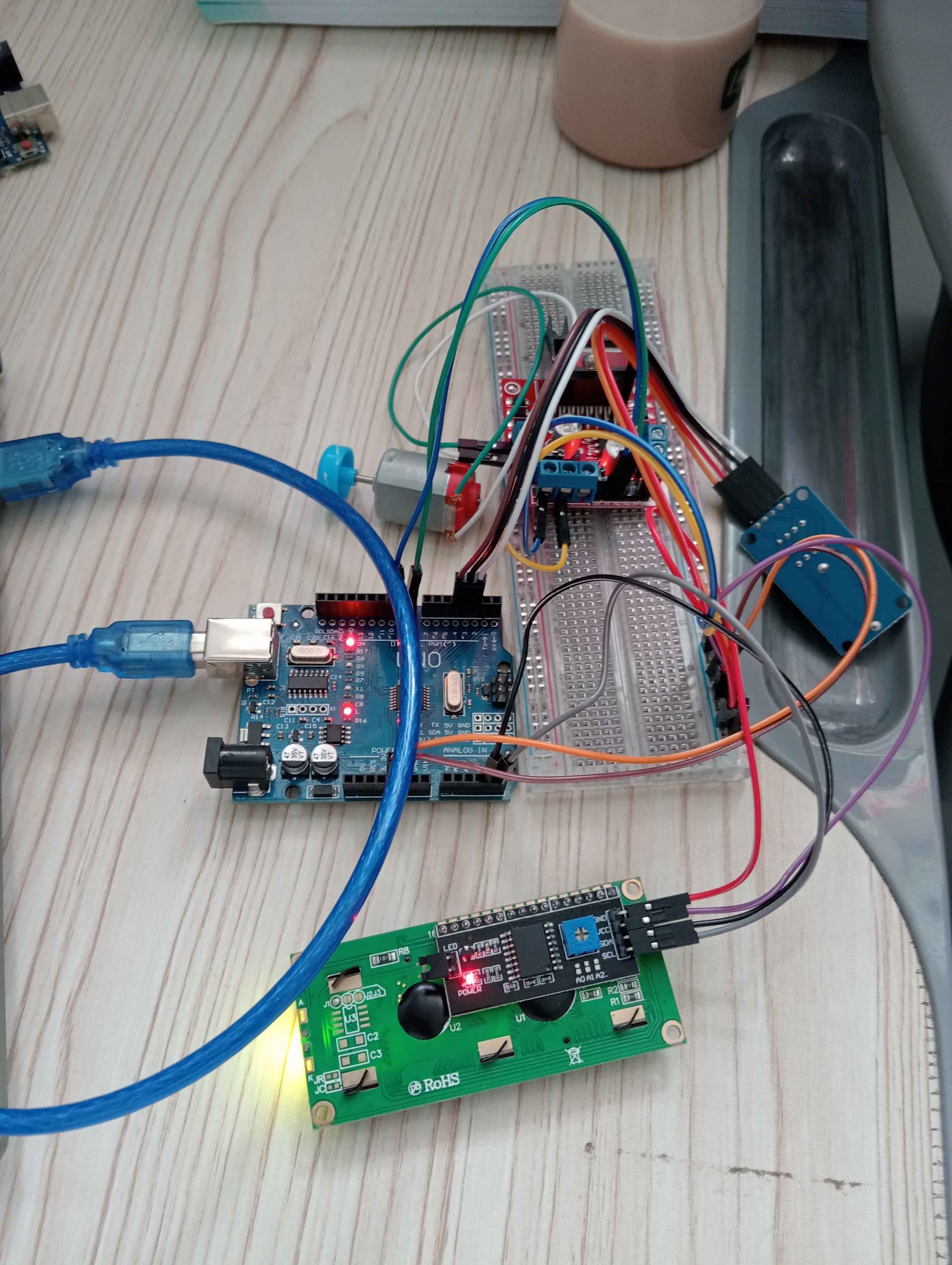
Please inform me if i had made any mistakes
THanks for any kind of help

