Hello, I am helping my kid with a science project. I have a capacitor bank of capacitors from disposable cameras. I need some way to discharge the capacitors periodically or when the voltage reaches a certain level. Radio Shack and Mouser electronics tell me I need some sort of circuit put together to do this. Is this a problem that an arduino product could help with? The capacitor bank reaches about 280 volts. I need it to discharge, recharge and then discharge again repeatedly on its own.
It doesn't really sound like a job for an Arduino. For one thing, you don't want to get those voltages anywhere near the Arduino, so alot of extra circuitry will be needed to protect it. Second thing is the sequence you describe is far too simple to need anything as complex and capable as a microcontroller.
What is the capacitor bank for, what does it do?
Paul
Is one side of the capacitor grounded, and if so, is it the positive or the negative side? If the negative side is grounded, then one way to discharge it is to use a high-voltage N-channel mosfet, with the source terminal connected to ground, the drain to the capacitor +ve terminal via a series resistor, and the gate connected to an Arduino digital output through another series resistor.
You can program the Arduino to turn on the mosfet periodically, or you can use a voltage divider to drop the 0-280V to 0-5V and feed that to an analog input pin, then you can turn the mosfet on when a certain voltage is reached.
Be very careful with capacitors charged to 280V - it doesn't sound to me like something your kid should be working with.
1 Like
Most power supplies have a resistor group that basically shorts the caps and allows them to discharge when the power is removed from the input. The resistors are large and will drop the power of the cap in about 30 seconds or so. I dont know if this is what you are looking for but it will make the circuit safe once power is removed but will have such a high resistance that it will be ignored while the circuit is in use... one of those paths of least resistance things. I'm not sure if this is your goal or if you are looking to create a rapid discharge circuit like the caps' former use as a camera flash.
Dom
The project is a small boat propelled by magnetohydrodynamic propulsion. There is a channel that goes through the middle of the boat. Magnets on each side of the channel creates a magnetic field. Copper electrodes on the top and bottom of the channel. The boat is in salt water. When power is supplied to the electrodes it creates an electrical field in the salt water that crosses the magnetic field. The result is a propulsive force in a third direction that pushes water out the channel. We have used a 9 volt battery and achieved a small amount of propulsion. A university professor suggested using a pulsing force and that is how the capacitor bank came into play. At first we thought the capacitor would charge to a certain level, then discharge. We found out that without a cutoff, the capacitor just constantly discharges and never builds up. Looking at the Lorentz formula, if you increase the voltage, you increase the force. A disposable camera will charge the capacitor bank up close to 300 volts. So a means to discharge the bank, allow for recharge and then subsequent discharge is what is needed. Someone at Radio Shack suggested a 555 timer, but it can only handle 18 volts. No one seems to make a timer that can handle the voltage.
Interesting project!
Salt water is a conductor of course, with conductance depending on the salinity, so there will always be current flowing through the water if there is a voltage across the channel. I would assume that Ohm's law holds unless you get a chemical reaction with the electrodes, that over time changes their surface conductivity.
Have you measured the resistance of the salt water channel? That would help to think about the charge/discharge rate of the capacitor.
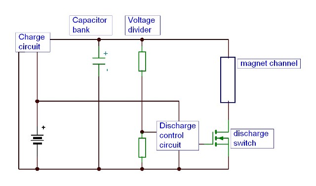
I would do it like this.
The voltage divider having a high resistance. The discharge control can be a micro controller or a 555.
nilton61:
I would do it like this.
The voltage divider having a high resistance. The discharge control can be a micro controller or a 555.
That looks OK to me, however the magnet channel will of necessity be at ground potential (because it is in contact with the water), which means that the discharge controller and battery will be at -300V prior to discharge. Not a problem if it is insulated and enclosed so that there is no danger of touching it. But I think it would be better to ground the discharge controller and switch the high side of the channel, again using a N-channel mosfet (because there are few P-channel mosfets rated above 250V). Use a chip such as http://uk.farnell.com/international-rectifier/irs2153dpbf/half-bridge-driver-self-osc-dip8/dp/1271804 to drive the mosfet.
However, I don't think you will get any more drive by discharging capacitors than by a steady direct current. The MHD force is Fmag = I (L × B) where I is the current, L is the distance over which the current passes, and B is the magnetic field. So it is the average current that matters. If you use a pulsed current, say twice the current for half of the time, you will get the same force, but double the power loss due to the resistance of the water. Therefore, I think it would be more efficient to use a steady current.
The component you are seeking is called a thyristor.
Paul__B:
The component you are seeking is called a thyristor.
Good point, I had forgotten about thyristors. You could use a thyristor as a high side switch, and drive it from an Arduino or a 555 using a pulse transformer. Simpler than using a mosfet and high-side switch IC. The complication is that the thyristor won't switch off until the current through it falls below its holding current. You may have to turn off the charging circuitry to achieve this.
If the turnoff threshold of scr is higher than the charging current it will work. otherwise it can be done like this.

This sounds like you need something to act like a trigger to drop the current to allow the field to discharge. Sounds like the ignition system from a car. When the points are closed the capacitor (called a condenser in automotive speak) charges up and the coil builds a magnetic field. When the points open the cap discharges through the coil giving is a boost which is enough power to excite the secondary windings in the coil and BOOM the fuel ignites. Modern ignitions use different methods of discharging the coil but the point type seems to fit this situation best.
How fast can you charge the cap? You could set the 555 timer circuit to activate a transistor that can handle the power you need to discharge the coil. This would be similar to the 70's and 80's style high energy ignitions only you would be using a 555 timer instead of a pickup coil in the distributor, the concept is the same all and all.
Dom
Here is a diagram of the boat. The cubes inside the boat are magnets. The parts sticking out the back of the boat channel are the electrodes. The magnets are not in the water. I'm new to using the Arduino. Which board would I use and how do I program it?

Most all arduinos can handle this task. The Mega has the most inputs and outputs, the Uno is one of the most popular because of its price and middle of the road in/outputs.
I am going to imagine that each of these coils I'd going to need to be fired sequentially. Again we go to the auto industry. The distributor less ignition systems fire individual coils in sequence based on some simple inputs. Also brushless motors use a system where they fire the field coils in order to have a cat and mouse effect on the coils and the rotor. I am also going to imagine some type of resonance will need to be found to get the most out of the system. With this you are going to have to find some type of system to trigger the coils in sequence with the power of the cap going through the coils. If this were a spark coil the extra power would be dissipated with the spark but in this case the coils will be the magnets, which will have to disipate the power somehow, prolly through heat at the magnets. You should be able to set up the arduino to initiate a sequential signal through the digital outputs. Then you would need a way to handle the power from the cap and send that through the magnet coils. Not sure if you would need a relay assembly or if it could be done with transistors, either way you are gonna need to isolate the low power side (Arduino) from the high power side (cap and coils).
Dom
MDMassey:
I am going to imagine that each of these coils I'd going to need to be fired sequentially.
This is a MHD thruster. Somewhat similar to a rail gun except that the "projectile" is water. The magnets are permanent. The discharge is through the water itself, transverse to the magnetic field and the water is propelled in the other transverse.
Paul__B:
MDMassey:
I am going to imagine that each of these coils I'd going to need to be fired sequentially.This is a MHD thruster. Somewhat similar to a rail gun except that the "projectile" is water. The magnets are permanent. The discharge is through the water itself, transverse to the magnetic field and the water is propelled in the other transverse.
If I understand a rail gun the magnets fire sequentially pulling the projectile with it while offering a repelling magnetic field behind the projectile to help accelerate it.
What you have in mind is a "coil gun". A rail gun, whilst having some similarities, is a completely different structure.
The corresponding Wikipedia articles detail this excellently. (No shortage of enthusiasts on such subjects!)