this is my 1st attempt at designing a simple low power arduino board.
The idea is to have it run off of 1 or 2 AA (AAA) batteries, or a small 3.6v rechargeable cell. with the option of external 5v (diode protection to the stepup circuit)
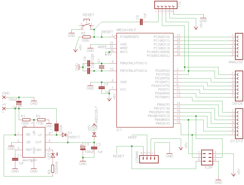
I have based the power part on the mintyboost circuit, and merged it with a minimal type arduino layout.
then tried to keep the board simple and nicely layed out
unfortunately it isnt arduino shieild compatible but im sure an adaptor can be made to get round that.
i made it mainly for compact reasons.
I have hand etched a single sided prototype that is more simple than the current design (pics soon), but due to size and complication the final will be 2 sided.
revisions will be made as i scope out exactly the components i'll be using (like the inductor), so bare in mind its still being developed
I am kinda new to pcb design so i wouldn't be surprised if i have made some mistakes here and there
if all goes well and i can find a place that can make up the boards for me cheap (when i finalise the design) I will build a few and may have boards for people to test and give feedback
I like it. You could bring the other two analog pins out to headers. Also it might make producing a shield adapter a little easier if you would move Aref and a ground over to the other side and arrange reset, power and ground in the same order as the Arduino boards. Add a cap to Avcc.
I might have some advice. I made this board about a year ago . . .
The first one I made did not have a ground plane and did not work. Almost like the crystal didn't start. Separately the switcher worked and so did the Arduino. My second attempt with a ground plane works fine and is a very handy board. So first suggestion - consider a ground plane.
My second suggestion in truth didn't work for me, but I may have did something wrong. The suggestion is to tie LBO pin on the MAX756 to the Reset line. The idea is to use it to hold reset and turn off the ATMega when the battery got low. (Looking at it again I may have the logic backwards.) Although I can't prove it was a good idea, I think it's worth considering.
I haven't seen any on the commercial boards either but Vcc is pretty noisy anyway because of all the digital and since you have a DC/DC converter yours will probably be a little noisier. The LC network will definitely help the performance of your analog section but is totally optional. The circuit is on page 258 of the ATmega data sheet.
Wow, that is really a nice concept. It's optimized for battery operation which I haven't seen in any of the other mini type boards. Suggest you go with the 328 chip as it really has become the base line processor these days and is not a real costly upgrade < $1.
One question. Is the +5vdc shown on the TTL connector leaving or entering the board? if the board was being powered by batteries and +5vdc was coming in from the TTL convertor connector (USB serial FTDI type chip) would that present any kind of problem?
thnx
that 5v would be exiting the board, if u are delivering power from that pin to the board then take take the battery out cos that would be bad i think :s
I use a homemade ttl to rs232 converter and that takes its 5v power from the board when in use. still need to test this on the prototype, am waiting for a few parts b4 i can tho..
I haven't tried a 328 yet, i just been using 168's, if the pins are the same then no reason why not.
the latest revision has a jumper on the power portion of the board to select between 5v and 3.3v operation if it is desired.
will be looking into how the low battery indicator thing works to see if it will shut off the 168 if tied to the reset somehow. still gotta see if the battery led does its job, it doesnt seem to work on the smaller cells i been trying. but they are prolly in dire need of a recharge XD
I don't know how much extra effort or components would be required but when using Li-po batteries it is very important that they are not allowed to discharge below around 3v per cell or permanent damage to the battery can result. An auto shutoff on low voltage would be very nice, however I guess a low voltage warning feature would be better then nothing, however an auto shutoff would be better for unattended operation of the board.
I know how to implement that feature with a small 5vdc auto latching relay and one digital output pin plus analog input reading the battery voltage, however that takes some code to placed into the users program and an external hardware only solution would be better in my opinion.
Anyway nice project you have going there, I will be sure to follow the thread.
thnx for the info on groundplanes i'll try and implement one on the final design
i'm kind of at a standstill right now while i assess what components i will be using, also i'm wondering if there is a cheaper alternative to the max756..
and can anyone suggest a cheap place online where i can get the boards made?
hmm anything much cheaper in the way of board fabrication i dont want too many boards XD?
edit:
Oh great -_- they sent me the wrong size chip sockets, so i gotta wait even longer to get that sorted out :S
still waiting for other components.
i hope they hurry up cos i want to get on with this design :3
hmm something seems to be wrong with my prototype :S the arduino portion isnt working for some reason.
this was the 0.0001 ver anyway so my later designs could be ok, but i need to find out whats wrong with this one and make sure its not in the later schematics :S
if anyone sees any discrepancies in the schematics i posted please let me know asap