Hello. So I just bought an Nodemcu esp8266 board with some wires and etc. As a programmer it does not seem hard at all to program some basic tasks. Played with LED's, server already. Now here comes the task which makes it all harder for me because Im not really much of the hardware person (till now I guess..?).
I have an garage/gate opener which runs on 3Volt cell battery (that flat one that looks like a cent).
As I read there are a couple of different ways that I should simulate this kind of openers pushbuttons.
Could someone help me to go thru stuff I will need to make it work..?
With my simple knowledge of Voltmeter I already mesured that when button is NOT pressed its hot with those 3Volts. When its pressed it goes to 0. I guess I cant just wire 2 wires from ESP8266 to it and set LOW/High statuses for that button..? Sorry if I seem like an idiot. But this s*it just amazed me today and Im gonna probably automate much more stuff in my house
It sounds like the push button on the garage/gate controller pulls low to activate the circuit.
If that is the case, the safest way to join the esp8266 and the remote control would probably be to use an opto coupler across the contacts of the button. The opto coupler would be connected to the esp using say a 330 ohm resistor.
You may also be able to use an esp pin directly. The esp and the controller would have to share a common ground. Use a resistor, again say 330 ohm, to limit the current if anything goes wrong.
6v6gt:
It sounds like the push button on the garage/gate controller pulls low to activate the circuit.
If that is the case, the safest way to join the esp8266 and the remote control would probably be to use an opto coupler across the contacts of the button. The opto coupler would be connected to the esp using say a 330 ohm resistor.
You may also be able to use an esp pin directly. The esp and the controller would have to share a common ground. Use a resistor, again say 330 ohm, to limit the current if anything goes wrong.
What do you think about the second method, should I watch out for continuity where is the + and where is the minus. Which part should I connect the Pin from arduino? Or should I try going with the mosfet/relay/optocoupler..? Im new in this so I might ask alot.
If the remote control button is like in the attached diagram, you probably can connect it as illustrated here, but you have to be careful.
To avoid any risk of backfeeding the battery in the remote unit, set the arduino pin to OUTPUT and LOW when activating the button and set the pin to INPUT (without pullup resistor) when not activating the button. You could also possibly use a schottky diode for additional protection. You could also possibly power the remote from the arduino's 3.3 volt supply.
The 330R resistor is to protect the arduino pin, for example in the case that the pin is in state output low and you apply 3.3 volts directly to it. There is a chance, though, that it interferes with the circuit you are driving.
Can you first measure the current between point X on the diagram and GND without any other connections to the remote control. It should be a few mA at most.
6v6gt:
If the remote control button is like in the attached diagram, you probably can connect it as illustrated here, but you have to be careful.
To avoid any risk of backfeeding the battery in the remote unit, set the arduino pin to OUTPUT and LOW when activating the button and set the pin to INPUT (without pullup resistor) when not activating the button. You could also possibly use a schottky diode for additional protection. You could also possibly power the remote from the arduino's 3.3 volt supply.
The 330R resistor is to protect the arduino pin, for example in the case that the pin is in state output low and you apply 3.3 volts directly to it. There is a chance, though, that it interferes with the circuit you are driving.
Can you first measure the current between point X on the diagram and GND without any other connections to the remote control. It should be a few mA at most.
35mA is too high for that circuit. You certainly can't use an Arduino pin directly. Important first is to make sure the button circuit is correctly understood.
Remove the battery from the remote unit, then check that one contact of the switch is connected to the device's negative battery contact. Use your multimeter on a low ohms scale. If there is no connection, try the positive battery contact.
6v6gt:
35mA is too high for that circuit. You certainly can't use an Arduino pin directly. Important first is to make sure the button circuit is correctly understood.
Remove the battery from the remote unit, then check that one contact of the switch is connected to the device's negative battery contact. Use your multimeter on a low ohms scale. If there is no connection, try the positive battery contact.
So I used the voltmeters beeping mode.
Remote Minus - button = value 0
Remote Plus - button = value goes up (Voltmeter RED rod on Remote +, Voltmetre Black rod on the button)
Used the ohm mode.
From Remote unit positive - push button left contact 1500ohm, right contact 800ohm
From remote unit negative - all 0;
Oh s**t completely ignore what I told you. I made a huuuuge mistake! I eff up the polarities. Going to take a picture right now and write up everything properly.....
So okay.
My Meter has (2000k, 200k, 20k, 2000, 200) Ohm modes. I used 2000.
Remote negative pad - Contact1 = 1475
Remote negative pad - Contact2 = 870
Anything with remote positve was 0.
I used my meters RED rod on negative pad and BLACK rod on the contact1,2 to measure it. If I swapped the polarities of the volt meter it stayed at 0.
EDIT: Also from the minus pad to the Contact1 it measures 0.15A
Ok. The picture is a good start.
I guess that if you replaced the battery in the remote and connected “contact1” and “contact2” together, the garage door (or what ever is connected to the receiver) would operate.
If that is the case, the most guaranteed way of integrating the esp with the remote is to use a relay module, connecting it across the push button contacts that you have marked. The NC pin of the relay module then stays unconnected.
Where did you measure the 35mA ?
When you say the meter gave a reading of 0 on the 2000 ohms scale, do you mean 0 ohms , that is, the meter display is exactly the same as if you touched the two meter probes together? Or the same as if the meter probes are not connected to anything?
With a CR2032 cell, the small contact is for the negative.
6v6gt:
Ok. The picture is a good start.
I guess that if you replaced the battery in the remote and connected “contact1” and “contact2” together, the garage door (or what ever is connected to the receiver) would operate.
If that is the case, the most guaranteed way of integrating the esp with the remote is to use a relay module, connecting it across the push button contacts that you have marked. The NC pin of the relay module then stays unconnected.
Where did you measure the 35mA ?
When you say the meter gave a reading of 0 on the 2000 ohms scale, do you mean 0 ohms , that is, the meter display is exactly the same as if you touched the two meter probes together? Or the same as if the meter probes are not connected to anything?
With a CR2032 cell, the small contact is for the negative.
Forget those 35mA I probably done some begginers mistake.
Yes if I would insert the battery and short out Contact1 and Contact2 the LED that indicates that it should open the gates Lights up.
If I used my meters RED probe on the positive remote unit battery contact and the BLACK probe on any of the contacts it stays as if the meter wasnt touching anything.
But if I used meters RED probe on the NEGATIVE remote unit battery contact and the BLACK probe on Connection1 it shows up as 1470 and on Connection2 as 870
EDIT: Also from the minus pad to the Contact1 it measures 0.15A
I’m guessing that the buttons are in a daisy chain and each, when pressed, bridges a resistor of a different value so the mcu can identify which is pressed.
You could maybe confirm that by (again with the battery removed) by measuring the resistance between contact1 and contact2, then do the same for the equivalent contacts on each of the other buttons. Notice that buttons 2, 3 and 4 are rotated through 90 degrees so measure between one upper and one lower pin of each button switch.
In any case, a relay module works work to bridge the button.
6v6gt:
I’m guessing that the buttons are in a daisy chain and each, when pressed, bridges a resistor of a different value so the mcu can identify which is pressed.
You could maybe confirm that by (again with the battery removed) by measuring the resistance between contact1 and contact2, then do the same for the equivalent contacts on each of the other buttons. Notice that buttons 2, 3 and 4 are rotated through 90 degrees so measure between one upper and one lower pin of each button switch.
In any case, a relay module works work to bridge the button.
Well between contact 1 and 2 its 0ohm(because its unclicked). And when clicked it just jumps to some value that I cannot mesure because of the small contacts and its kinda hard to hold the rods to it and press the button at the same time.
When clicked all buttons shows up around 3.5 to 4.3 Ohms on (200 mode on Voltmeter because 2000 is too much)
Yes if I would insert the battery and short out Contact1 and Contact2 the LED that indicates that it should open the gates Lights up.
This from post #13 appears to contradict it:
Well between contact 1 and 2 its 0ohm(because its unclicked).
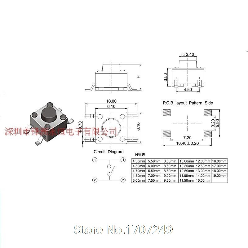
You've understood how these tactile button switches are constructed. Pairs of pins are internally connected.
When measuring, it is important to measure 2 pins which are not connected together.
Uisually, these switches are push-to-make. That is the contact is made when the button is depressed. It is unusual, but probably not impossible, to find tactile switches which break the contact when pressed.
While Im waiting for parts. In this PCB there is a PCB antenna. And on one of the remotes for some reason it functions poorly. Does not go the huge ranges my other one goes. Is there a way to "boost" atleast a little bit an PCB antena? Maybe soldering a wire on it or smth?