Behaviour of the serial port on the ESP32S2

Can anyone tell me why this behaves erratically on the ESP32S2 Mini?

Doesn't matter whether I use the Arduino serial port version:

void setup() {
  Serial.begin(115200);
}

void loop() {
  Serial.println("Hello :-)");
  delay(1000);
}

Or the USB CDC port version:

#include <USB.h>

USBCDC USBSerial;

void setup() {
  // put your setup code here, to run once:
  USB.begin();
  USBSerial.begin();
}

void loop() {
  // put your main code here, to run repeatedly:
  USBSerial.println("Hello :-)");
  delay(1000);
}

The ESP32 is directly connected to USB without a UART so its using its own native ESP32 CDC port.

The first example has sometimes displayed the output even after the ESP32S2 has been power cycled, but is unpredictable. For 90% of the time is shows no output at all. The second example displays nothing at all after a power cycle The exception is in Serial Monitor (IDE2.x.x) where both examples will display something, but only after reset has been pressed.

Both were compiled with 'Tools -> Use CDC on Boot: Enabled' set. I rather suspect the Espressif CDC code in the ESP32 firmware, but wondering why I can't get a stable USB connection on power up. Unlike the Serial Monitor, most applications just drop the serial connection on reset so I can't get a consistently working serial port.
The microcontroller is fast, compared to the time it takes USB to do all the USB negotiations that set up a CDC device or other "virtual com port", so the loop() starts executing before things are "ready."

If there is a chance that your sketch will run on native USB boards. you should set up the "Serial" port with a loop, waiting for initialization:

void setup() {
  Serial.begin(115200);
  while (!Serial) {
     ;  // busy wait for USB
  }
}

(If there's a chance that you sketch needs to run when the board is NOT connected to a computer, the loop should have some sort of timeout.)

void setup() {
  Serial.begin(115200);
  delay(1000);
}

Better ?

void setup() {
  Serial.begin(115200);
  while (!Serial) {
     ;  // busy wait for USB
  }

works, too (harder for me to commit to memory).
}

Thanks, but I have read that the loop approach does not work on an ESP32 CDC port? Apparently it only works on AVR boards with a hardware serial port? However I did try a delay:

void setup() {
  Serial.begin(115200);
  delay(1000);
  Serial.flush();
}

void loop() {
  Serial.println("Hello :-)");
  delay(1000);
}

It has made no difference. The board still starts with no apparently active serial port. I do see /dev/ttyACM0 port, but no output coming from it when I connect to it with PuTTy.

Even without a delay I would have thought some output would appear sooner or later since the "Hello" message is in a loop, so I am struggling with why I get absolutely nothing?

Aside from the upload procedure, do these native ESP ports work differently to a UART?

PS, I did notice that there is also an 'ESP32S2 Native USB' option which I tried but I then get no /dev/ttyACM0 at all! Unfortunately this board option does not show the have the 'Tools -> Use CDC on Boot:' setting that comes up when the 'ESP32S2 Dev Module' option is selected. I am therefore uncertain which one I should be using.

Add a delay before initializing USB.

One other thing I am curious about - in a lot of examples its shown this way round. Why is serial being initialised before USB? Does it matter? I did try it both ways around but no difference so maybe that answers my question, but wondering which is correct?

BTW, I have noticed that there is an SMD component in the serial bus path marked V05, which appears to be a TVS diode array for ESD protection. Might this be interfering with normal operation somehow?

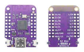
This is my ESP32S2 (V1.0.0) Board (Fig-1):


Figure-1:

To recognize the COMX Port, press and hold SW-0 and then press and release SW-RST and then release SW-0.

I had similar problem back in 2024 which I have solved in the following way:
Why is Serial Port of ESP32 S2 Mini Board not communicating with MCU after uploading?.._gaNDk2MDY4NzA4LjE3NTAwNjE3OTg._ga_NEXN8H46L5czE3NTAwNjE3OTgkbzEkZzAkdDE3NTAwNjE3OTgkajYwJGwwJGgxNTE1NDg1MzA5

Finally, the problem is solved having that Serial Port (UART0) of ESP32 S2 communicates in both ways. After uploading, press and release the SW-RST.
IDE 2.2.1 (Apparently, it is IDE 2.2.1 that works and NOT IDE 1.8.19.)

Tools' Menu Settings:
Board selected: ESP32S2 Dev Module
USB CDC On Boot: "Enabled" //Option: Disabled
Port: "COM6"
Upload Mode: "UART0" //option: Internal USB
Sketch is compiled/uploaded

Sketch:

#define LED 15

void setup() {
  Serial.begin(115200);
  pinMode(LED, OUTPUT);
}

void loop() {
  digitalWrite(LED, HIGH);
  delay(1000);
  digitalWrite(LED, LOW);
  delay(1000);
  Serial.println("Hello");
}
Serial Monitor Output along with LED blinking:
11:26:01.625 -> Hello
11:26:03.614 -> Hello
11:26:05.619 -> Hello
11:26:07.631 -> Hello
11:26:09.629 -> Hello

The following sketch also works tested today 16/6/2025) for two-way serial communication of Serial0 Port.

char myData[20];

void setup() {
  Serial.begin(921600);
  // initialize digital pin LED_BUILTIN as an output.
  pinMode(15, OUTPUT);
}

// the loop function runs over and over again forever
void loop() {

  digitalWrite(15, HIGH);  // turn onBoard LED 
  delay(1000);             // wait for a second
  digitalWrite(15, LOW);   // turn off onBoard LED
  delay(1000);             // wait for a second

  byte n = Serial.available(); //receive string from InputBox of Serial Monitor
  if (n != 0) {
    byte m = Serial.readBytesUntil('\n', myData, sizeof myData - 1);
    myData[m] = '\0'; //null character
    Serial.println(myData); //Send back the received string to OutputBox of SM
  }
}
14:11:10.230 -> Hello
14:11:24.276 -> How are You?

During uploading, the Serial Port connection is erratic?

Golam, thank you. I don't have an ESP32S2, but I did acquire an ESP32C3 Mini recently for testing. These are a very similar small board to your ESP32S2, although obviously with a different variant of the MCU, but crucially without a UART onboard. I uploaded the same code (first snippet but with added delay) as above to this board as I did to the S2 and it worked as might be expected. The second snippet does not compile and complains about USBCDC not being defined which I need to investigate further.

For some reason the S2 behaves differently. Then again, I have been reading that it is not officially supported despite being listed among the variants, so perhaps I shouldn't expect too much?

Please, change your thread title to "........ ESP32C3".

Sorry for the confusion. Your board looks different to my modules and I thought it was a different board, but its actually the same thing in a different package. They both have the S2 chip. I have edited my previous post. The problem as originally reported is with the two ESP32S2 modules that I have. The C3 had been used only for test and comparison purposes and works OK. Ideally I would like to get the S2 working properly as well.

Your first snippet is not that different to mine except that you have some GPIO activity to blink the LED going on. BTW, if I disable USB CDC On Boot then I get nothing at all, so that doesn't seem to be a viable option, but maybe understandable if you are using a UART via the other Serial port. If its enabled, I do at least get something in Serial Monitor, but only after pressing reset.

Can I confirm that you go it working via the onboard USB port, or did you have to use the UART board to communicate properly with it? Which version of the Espressif Arduino core was that with?

BTW, I tried your second sketch, then one that reads and responds. Thank you for that. Very useful for testing. With the S2 it worked in Serial Monitor, but not in any other terminal unfortunately.