wildbill:
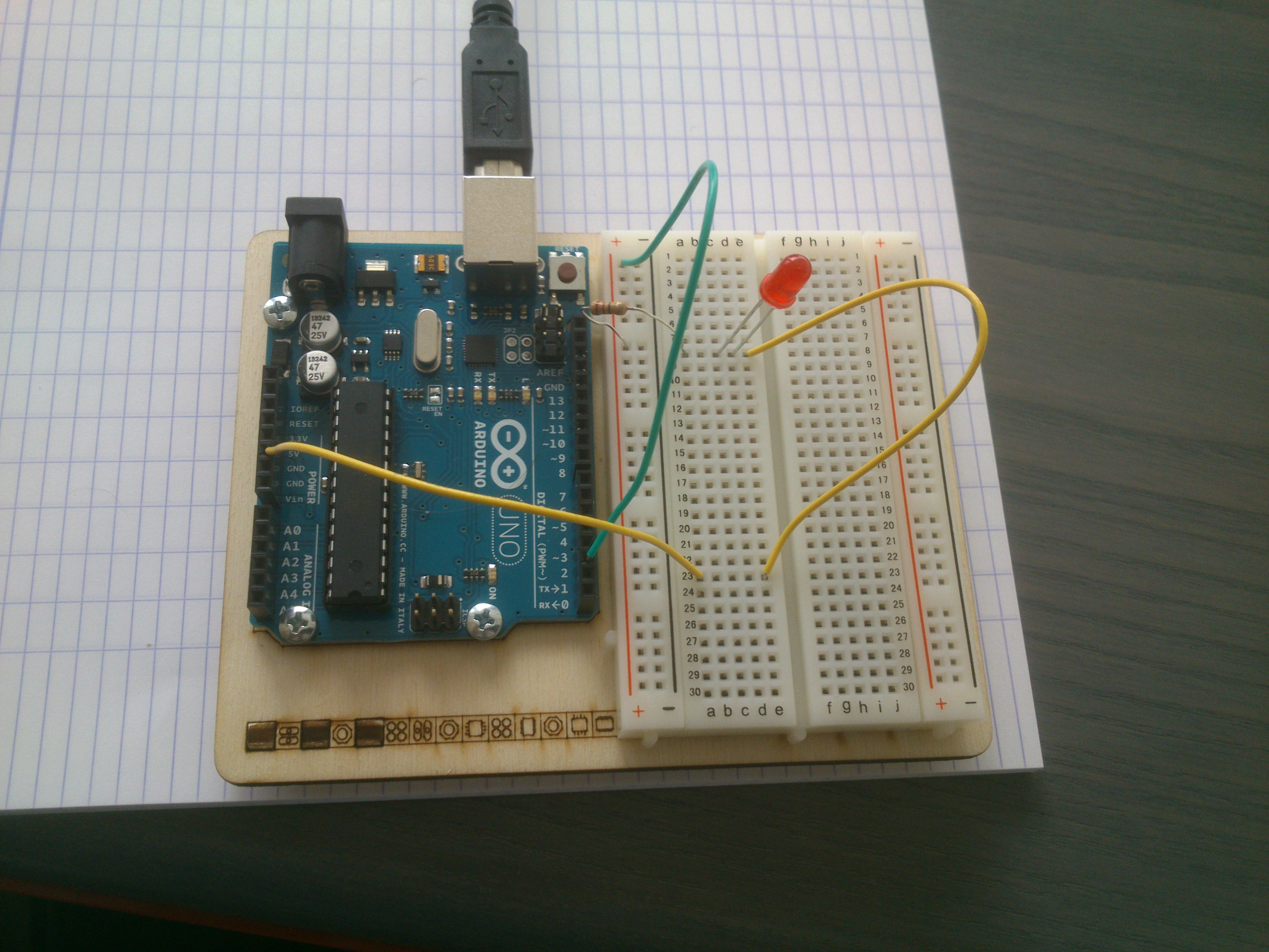
Ledpin is 2. The green wire appears to be plugged into pin 3.
No I think it's right: a parallax thing in the photo.
Maybe the LED's in back to front..... it's reverse logic the way it's wired: pin high is off with the other (edit: ie right hand) side of the LED to the 5v.
Edit: CRAP now I'm making parallax errors: the wire IS in gnd... but it could still be that the LEDs back to front.. 8)
Test the code by changing LEDpin to 13 and see if the on-board led works.
If it does, move the wire from pin 2 to 13, see if the external one lights up
And /or put that wire into the 5v and the external led should light up cos it's got 5v hardwired.
If you have a meter, take the wire out of pin 2 and measure the resistance from the end of that wire to the left hand leg of the led to make sure the resistor is firmly in the holes: you should read its nominal resistance. (I can't make out the colours: what resistance is it, btw?)
Edit: for the record I have your exact copied and pasted code and a hook up of the exact circuit, compiled uploaded and running correctly even as we speak. So I'm guessing a break in the circuit somehow, maybe those wires are faulty, open circuit resistor, maybe the led doesn't actually work?
Another test: leave the wires in pin2 and ground, but free the other ends from the board and put your voltmeter across there: you should see 5v come and go....
WilfriedPannen:
turn the LED 90 degrees in the breadboard
Oh crap how could I have missed that.... the circuit I made isn't exactly like his, I had my led over the break to the power rail... (I cheated and used an led to which I had already soldered a resistor)....
Well spotted Wilfried...
(What Wilfried means, Ardinateur, is to put the left hand lead of the LED in the row above, and have the resistor in that row to the power rail. Right now, the two leads of the LED are joined together in the same row...... )
Thanks all of you! The problem was indeed the LED. Works perfectly now.
Am I right that the reason for the LED not working was that electricity chooses the path of least resistance so the LED was ignored?