Built-In LED interference

Ok, so this is a general discussion on using pretty much any board with a "built-in" LED.

I'm using a Wemos D1 Mini on this project, and the built-in LED is connected to pin 4.

Now if I want to use that pin as an input, it interferes with my uploading of sketches, the IDE can't acquire the serial port while the input is low.

Perhaps my issue is related only to the Wemos, or it may be a general issue, I've not noticed the problem on other boards to be honest.

I can, if necessary, move my input to another pin, but it'll mean a hack on my PCB, which I'd like to avoid, for obvious reasons.

Can anyone advise how to proceed please....

If you don't need it then remove the built-in LED

On another thread about the UNO, it states that the LED is buffered with an op-amp, so I don't see how removing the LED can change the behaviour of the pin...

On my project I have the pin connected to a keyswitch that pulls the input low when switched on, and there is a 10K pullup to 3V3. On the Wemos D1 Mini, the only input that has an internal pullup, (and it's permanently enabled) is D3.

The in-built LED is ON when the keyswitch is ON, meaning D4 is pulled to GND. When the switch is OFF, the input voltage is 1.3V, and I would have expected it to be 3.3V. This seems to shout at me that the LED is not buffered at all,

My current train of thought is that the LED is not buffered in any fashion, and I'm probably measuring the cathode voltage of the LED.

I think, therefore, I am going to avoid using D4 for my keyswitch as it is causing issues with uploading...

But you are not using a Uno

If it is not buffered then why not remove it ?

1 Like

That is true, has nothing to do with the LED.
Pin 4 is connected to GPIO2 which is a strapping pin

1 Like

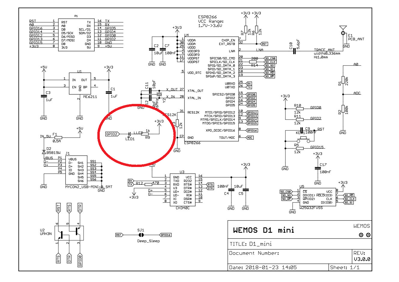
There is a 1K resistor connected between the LED and +3.3V.
When using this pin as an input, there may actually be some voltage on the pin.
Can you post the schematic of your project?

This is your Wemos D1 Mini?
See the schematic to see how the LED is wired.

This is Wemos D1 Mini schematic..

1 Like

What is a "strapping pin" ?

Removing it makes the board "non-standard", and replacing (if necessary) becomes an issue, besides which the LED is useful as a reference for uploading ...

It's one of the pins that determines the booting mode.
Need to be high during boot

I have moved D3 and D4 to D7 and D8, issue solved ... Of course I have to "patch" the PCB now, but I'd rather have that scenario than uploading issues, depending on whether the keyswitch is ON or OFF.

It seems that holding D4 low with the keyswitch (which incidentally lights the built-in LED), prevents the IDE from resetting the board for the upload.

As I said it's a strapping pin that need to be high during boot.
Should have read the documentation before you made a PCB

1 Like

Pins used during Boot

The ESP8266 can be prevented from booting if some pins are pulled LOW or HIGH. The following list shows the state of the following pins on BOOT:

  • GPIO16: pin is high at BOOT
  • GPIO0: boot failure if pulled LOW
  • GPIO2: pin is high on BOOT, boot failure if pulled LOW <<<-------- D4
  • GPIO15: boot failure if pulled HIGH
  • GPIO3: pin is high at BOOT
  • GPIO1: pin is high at BOOT, boot failure if pulled LOW
  • GPIO10: pin is high at BOOT
  • GPIO9: pin is high at BOOT

ref: ESP8266 Pinout Reference: Which GPIO pins should you use? | Random Nerd Tutorials

1 Like

Which is exactly as I've discovered - oh well, I will know for the future, not using D4 now....

Which other pins are "strapping pins" ?

It's a PCB I'm using from a previous project, not 100% but close enough not to need another PCB design.

I'm only using 2 inputs, and SCL/SDA for an LCD with I2C interface.

See post #12

This topic was automatically closed 180 days after the last reply. New replies are no longer allowed.