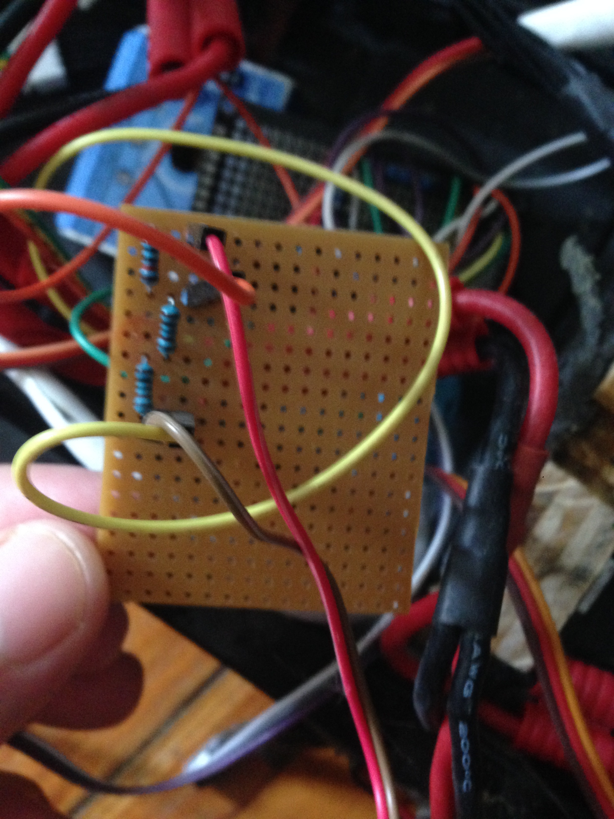
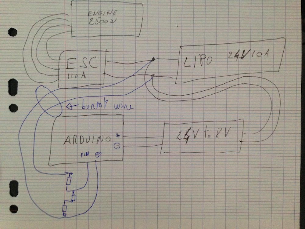
I use an arduino to send through bluetooth voltage (% batt), speed and battery temperature of my homemade electric scooter to my iPhone. The thing is that the wire of the voltmeter setup burn as well as the HM-10 BLE module when I push the throttle too hard. I think it's a current load issue but I can't figure out what's wrong. I guess it's because the arduino is powered by the same battery I want to get the voltage but I'm too noob to figure out. Here is the schematics (well sort of...).
I've got to guess it's not wired the way you think it's wired... It should be impossible to burn-up the wires without burning-up the resistors first.
What's the value (Ohms) of those resistors?
Does the Arduino still work? i.e. Does the Blink LED sketch load & run?
when I push the throttle too hard.
That doesn't make sense either... If anything happens to the battery voltage at full-throttle, the voltage should drop. And, the current through the motor doesn't pass through those wires. The wires to the motor might burn-up, but not the wires to the Arduino.
You may have used the wrong resistor values for the voltage divider. You might have calculated the wrong ratio (giving you a much higher output than 5V max), AND/OR you have the correct ratio, but the wrong order of magnitude for each. The latter would give a correct output voltage, but would dissipate WAY TOO much power through the resistors, thus burning them (and the wire) out.
NOTE: DO NOT USE VOLTAGE DIVIDERS FOR MEASURING VOLTAGES - USE ZENER DIODES IN SERIES.
True ! Sorry R1 = 10K so R1 +R2 = 12K ~ 11.96K
I guess I put 11.96 because I measured the all thing around this value.
I did this a long time ago I'm a little bit confused.
zeners are normally +/- 5%, but that's only at their rated current - they have quite a high 'knee' resistance - and used with varying currents as this application requires means that this will be significant.
Their temperature coeficient is awful.
If you want to use an offset a bandgap reference is much better, and bandgap-derived devices such as TL431's are useful too.
But 1% resistors with 100ppm tempco are cheap and reliable.
Unless you want make a crude bar led meter, no zeners are used.
Google for Voltmeter Circuit images and you will see example after example of Voltage Dividers. This is a primary use case for voltage dividers and not the one it often mistakenly gets used for (lowering a voltage to be used as a power source)
Power_Broker:
You may have used the wrong resistor values for the voltage divider. You might have calculated the wrong ratio (giving you a much higher output than 5V max), AND/OR you have the correct ratio, but the wrong order of magnitude for each. The latter would give a correct output voltage, but would dissipate WAY TOO much power through the resistors, thus burning them (and the wire) out.
NOTE: DO NOT USE VOLTAGE DIVIDERS FOR MEASURING VOLTAGES - USE ZENER DIODES IN SERIES.
No, use voltage divider for several important reasons, like it will work and it won't instantly blow up your Arduino on (reasonalbe amounts of) over-voltage.
Ok, ya'll bring up some fair points, but most of them can be addressed if you use a high input impedance buffer between the zener and the analog input. This will prevent almost any current from flowing through the zener (limiting the knee effect) and will isolate/protect any down-stream circuits from any overvoltage.
Hi,
Can I suggest that you install some fuses in that arrangement. Not just the voltage lead to the potential divider but also to the input of the 24-5 DC-DC converter.
That way you are helping to prevent ELECTRICAL FIRES, you need to understand that you are working with a battery that is capable of some pretty HIGH SHORT CIRCUIT currents, capable of starting a fire, Lipo fires are not pleasant.
Install the fuses as close to the battery terminals as possible.
The bright red color makes very nice fireworks. And the smoke is mostly lithium oxide aerosol, which becomes powerfully caustic upon contact with the mucus membranes of your airway!