Button debouncing using bit shifting

The sketch below debounces a button and uses software interrupts. My question is about the bool debounce(void) function itself. Could somebody explain what it does?? Thanks. AA

#define LED_PIN  13
#define BTN_PIN  8
#define INT0_PIN 2
 
unsigned long T1 = 0, T2 = 0;

void INT0_ISR(void) {
  digitalWrite(LED_PIN, !digitalRead(LED_PIN));
}
 
void setup() {
  pinMode(LED_PIN, OUTPUT);
  pinMode(BTN_PIN, INPUT);
  pinMode(INT0_PIN, OUTPUT);
  attachInterrupt(digitalPinToInterrupt(INT0_PIN), INT0_ISR, RISING);
}
 
void loop() {
  T2 = millis();
  if( (T2-T1) >= 5 )   {
    if (debounce()) {
      digitalWrite(INT0_PIN, LOW);
      delay(1);
      digitalWrite(INT0_PIN, HIGH);
    }
    T1 = millis();
  }
}
 
bool debounce(void) {
  static uint16_t btnState = 0;
  btnState = (btnState<<1) | (!digitalRead(BTN_PIN));
  return (btnState == 0xFFF0);
}

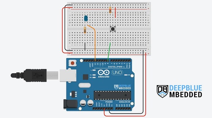
Here is the wiring.

While a long read, and more than you wanted, I recommend:

That is a thorough background, while the second half details what you want, I think. They're best read together, with a vat of coffee at hand.

4 Likes
  • As a side note, switches can be de-bounced by simply scanning them every few milliseconds, 20 to 50ms is sufficient.

  • Suggest you get into the habit of looking at a switch change in state rather than the switch current state.

  • Interrupts are for fast events, not for slow devices like switches.

1 Like

If a button does not bounce on press, you get the below states
Pressed no bounce

0000000000000001  1
0000000000000011  3
0000000000000111  7
0000000000001111  F
0000000000011111  1F
0000000000111111  3F
0000000001111111  7F
0000000011111111  FF
0000000111111111  1FF
0000001111111111  3FF
0000011111111111  7FF
0000111111111111  FFF
0001111111111111  1FFF
0011111111111111  3FFF
0111111111111111  7FFF

This is a perfect sequence.

If a button bounces on press, you het e.g. the below sequence (<< indicates the first bounce)
Pressed with bounce

0000000000000001  0x1
0000000000000010  0x2 <<
0000000000000100  0x4
0000000000001000  0x8
0000000000010001  0x11
0000000000100011  0x23
0000000001000111  0x47
0000000010001111  0x8F
0000000100011111  0x11F
0000001000111111  0x23F
0000010001111111  0x47F
0000100011111111  0x8FF
0001000111111111  0x11FF
0010001111111111  0x23FF
0100011111111111  0x47FF
1000111111111111  0x8FFF
0001111111111111  0x1FFF
0011111111111111  0x3FFF
0111111111111111  0x7FFF
1111111111111111  0xFFFF

The sequence will eventually reach 0xFFFF but it takes a bit longer.

If a button does not bounce on release, you get the below states (the * before 0xFFF0 indicates that the function will return true)
Released no bounce

1111111111111111  FFFF
1111111111111110  FFFE
1111111111111100  FFFC
1111111111111000  FFF8
1111111111110000 *FFF0
1111111111100000  FFE0
1111111111000000  FFC0
1111111110000000  FF80
1111111100000000  FF00
1111111000000000  FE00
1111110000000000  FC00
1111100000000000  F800
1111000000000000  F000
1110000000000000  E000
1100000000000000  C000
1000000000000000  8000
0000000000000000  0

Again a perfect sequence.

If a button bounces on release, you can get the below states (<< indicates the first bounce)
Released with bounce

1111111111111111  FFFF
1111111111111110  FFFE
1111111111111101  FFFD <<
1111111111111011  FFFB
1111111111110111  FFF7
1111111111101110  FFEE
1111111111011100  FFDC
1111111110111000  FFB8
1111111101110000  FF70
1111111011100000  FEE0
1111110111000000  FDC0
1111101110000000  FB80
1111011100000000  F700
1110111000000000  EE00
1101110000000000  DC00
1011100000000000  B800
0111000000000000  7000
1110000000000000  E000
1100000000000000  C000
1000000000000000  8000
0000000000000000  0

Note that the state will never become 0xFFF0.

Note:
0xFFFF and 0x0000 (the last line in each block) will be repeated endlessly till the button changes from pressed to released or vice versa.

The modified debounce function that will show the above sequences

bool debounce(void)
{
  static uint16_t btnState = 0;
  static uint16_t oldState = 0;
  btnState = (btnState << 1) | !digitalRead(BTN_PIN) /* | 0xE000 */;
  if (btnState != oldState)
  {
    oldState = btnState;
    printBin16(btnState);
    //Serial.println(btnState, BIN);

    if (btnState == 0xFFF0) Serial.print(" *");
    else Serial.print("  ");

    Serial.println(btnState, HEX);
  }
  return (btnState == 0xFFF0);
}

And the function to print in binatry with leading zeroes

void printBin16(uint16_t val)
{
  uint16_t x = 0x8000;
  while (x > 1)
  {
    if (val < x) Serial.print("0");
    x >>= 1;
  }
  Serial.print(val, BIN);
}
5 Likes

Something I learned again when I refreshed my acquaintance with this algorithm is that you cannot look at the switch too fast.

So the rate limiting accomplished by millis() is essential and informs the total time it takes to debounce the switch.

This algorithm is seen run on a timer interrupt. Not here. I don't mean to suggest.

As for the use of interrupts in this sketch, I see

  pinMode(INT0_PIN, OUTPUT);
  attachInterrupt(digitalPinToInterrupt(INT0_PIN), INT0_ISR, RISING);

The service routine toggles the LED, and is fired when the switch has been debounced.

Which seems like a long way to go to toggle the LED.

I'd have to classify this debouncing as curiously interesting, I haven't seen it in the wild much.

I needed help recalling its niche. chatGPT listed a few, and I spotted the one I was not remembering

chatGPT says it just fine; I haven't had time to do anything with FPGA and the way things are going will never.

chatGPT on:

FPGAs are where this bit-shift debouncing method truly shines.

In hardware design, especially with VHDL or Verilog, using a shift register to debounce inputs is very natural:

  • You already think in terms of bits and flip-flops.
  • You can easily clock in input samples on every system clock or a divided tick (e.g., every 1ms).
  • Detection becomes just a simple comparison (reg == 0xFF or reg == 0x00).
  • It avoids needing any counters or delays — it's just logic gates and flip-flops.

This method is synchronous, deterministic, and very resource-light, which is gold in FPGA design, where you often care deeply about timing, area, and stability.

chatGPT off.

a7

The sketch is worthless nonsense. If you try to understand it you will only confuse yourself. Do not try to learn anything from it, except maybe how not to do things.

Why are you studying this code? What are you trying to achieve?

2 Likes

:rofl:

Tested on Wokwi, as written it is looking for 7ms stable period after a change to make debounce. That period could be shorter.

// button  3/5/25
// this is beginner code
// written for Uno Rev 3

const byte buttonPin = 7;  // PIND bit 7
byte  pin7history = 0xFF;

void setup()
{
  Serial.begin( 115200 );
  Serial.println( F( "\n\nButton\n " ));
  
  pinMode( buttonPin, INPUT_PULLUP );
}


void button()
{
  static byte  prevMillis;

  if ( prevMillis != (byte) millis())
  {
    pin7history = pin7history << 1;
    pin7history += digitalRead( buttonPin );
    prevMillis = (byte) millis();
  }
}

void loop()
{
  button();

  switch ( pin7history )
  {
    case 0x7F :
    Serial.print( F( "button release " ));
    Serial.println( millis());
    pin7history = 0xFF;
    break;

    case 0x80 :
    Serial.print( F( "button press " ));
    Serial.println( millis());
    pin7history = 0;
    break;
  }
}

A perfect analysis and description, congratulations!

Anyway, that method (the one included in the OP code) to implement a debounce algorythm IMO looks like building a radar-guided laser to kill mosquitos, instead of just using a chinese electric killer racket.
The method relies on a pretty fast button check to detect consecutive status readings, and if the call rate is greater than 30-40 ms, it becomes completely useless compared to plain old methods like a small delay() after a state change or checking the status again after a few ms using millis(). Or an old good physical debounce circuit in my opinion is the best solution ever.

Thanks a million for the replies, very helpful. I read somewhere that the sketch I posted was introduced by Jack Ganssle in his article about button debouncing Debouncing, hardware and software, part 2. In my experience it works like a charm. Now I need to read the posts here and, hopefully, understand why it does... :grinning_face:

Thank you for the detailed explanation. Great!!

Every time I print, I invariably get this 1st line of white squares printed, e.g.:
15:28:48.479 -> □□□□□□□□□□□□□□□□□□□□□□□□□□□□□□□□□□□□□□□□□□□□□□□....
and then I get the first output from printBin16 which is 0000000000000001 1
Why are these squares printed??

What is supposed to print instead of squares?

Nothing I guess

Can you post the sketch?

Which you were directed to in post #2. How thoughtful.

2 Likes

BTW, I read Debouncing Contacts and Switches, thank you. But I could not find any reference to the printed white squares that I'm referring to, which seem to be related to Serial.print(...) somehow.

Often a sketch will try to print before Serial is fully initialized.
put this line:

while(!Serial);  // Read as: while not Serial

after Serial.begin;
it prevents the sketch from continuing until Serial is ready.

1 Like

Still prints the square characters �����������������

I'll bet you put it after the first print statement. Show us setup(), please.