i have a counter and a reset, as well as a 4 digit 7 segement display going with a alarm buzzer at the end of the count.
With all my digital pins used up ive been trying to use the analog pins in order to detect button presses that allow a incremental increase in the counterStop limit ive set.
HOWEVER, i can't seem to get the controller to read the input whether its set as analogRead or digitalRead its not seeing it all. Im using a arduino nano ive tried all the pins even using A6 as a analogRead pin and im not getting anything.
Im thinking my coding is just missing something but i am to new to see it after looking over all the examples and everything. You'd think if i could get this far i could program a dang button but apparently i have to much air inbetween my ears currently lol. If anyone could take a look over my code i would greatly appreciate it. Please and thank you.`
SevSeg sevseg; //Instantiate a seven segment controller object
const int button = A1;
const int siren = A5;
const int knockSensor = A7;
const int threshold = 1000;
int sensorReading = 0;
int counter = 0;
int counterStop = 10;
int buttonState = 0;


void setup() {
  byte numDigits = 4;
  byte digitPins[] = {10,11,12,13};
  byte segmentPins[] = {9,2,3,5,6,8,7,4};
  bool resistorsOnSegments = true; // 'false' means resistors are on digit pins
  byte hardwareConfig = COMMON_ANODE; // See README.md for options
  bool updateWithDelays = false; // Default 'false' is Recommended
  bool leadingZeros = false; // Use 'true' if you'd like to keep the leading zeros
  bool disableDecPoint = false; // Use 'true' if your decimal point doesn't exist or isn't connected
  pinMode (siren,OUTPUT);
  pinMode(A1,INPUT);

  sevseg.begin(hardwareConfig, numDigits, digitPins, segmentPins, resistorsOnSegments,
  updateWithDelays, leadingZeros, disableDecPoint);
  sevseg.setBrightness(90);
  Serial.begin(9600);
}

void loop() {
  // read the sensor and store it in the variable sensorReading:
  buttonState = digitalRead(button);
       if(buttonState==HIGH){
            counterStop==counterStop+counterStop;
           }
  sensorReading = analogRead(knockSensor);
    if (sensorReading>=threshold){
      counter== counter++;
      delay(10);
      Serial.println(counter);
      Serial.println(counterStop);

             if (counter== counterStop){
               digitalWrite(siren,HIGH);
               delay(5000);
                   digitalWrite(siren,LOW);
                    counter=0;
           }

      sevseg.setNumber(counter);
    }
    sevseg.refreshDisplay();
  }


/// END ///

type or paste code here
Let me guess; a simple pushbutton tied to 5V, with no pull down resistor anywhere in sight?
If that's the case: wire your pushbutton to ground, use pinMode(A1, INPUT_PULLUP); and invert the test of your button state. It'll save much hair pulling in the long term.
Maybe you know this already, but in general, Arduino analog pins can also be used as digital input or output pins. But there are a few exceptions. A6 & A7 pins on classic Nano V3 cannot be used as digital inputs or outputs, only as analog inputs.
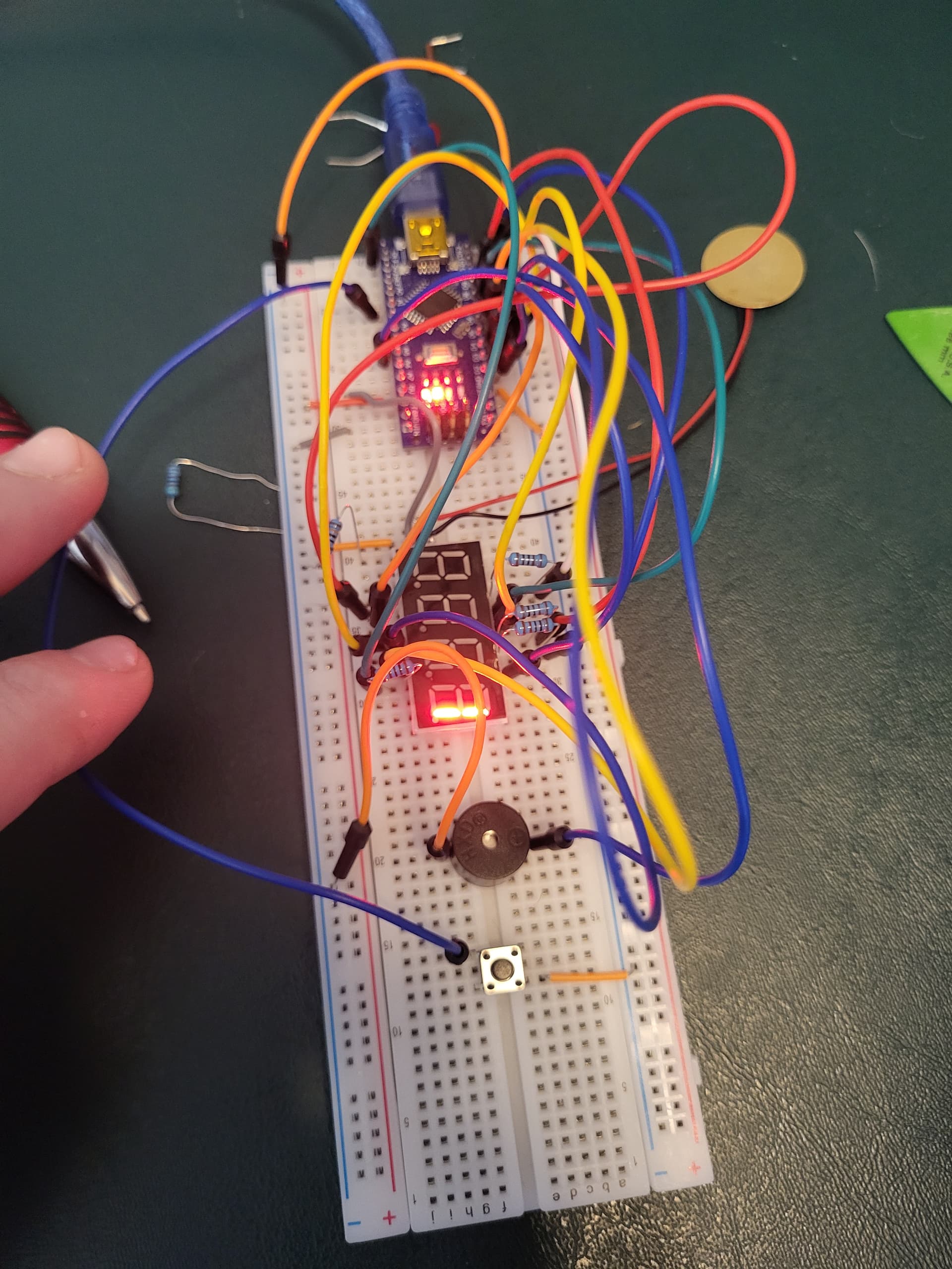
Heres what the circuit at the button looks like. Ive tried it with and without the resistor. Tried it with switching the pin number from A1 to 15 and switching the state to low instead of high. Something is wrong but i can't see the problem
The button is sideways to how most people use it. It made me blink.
But more importantly; I see a pullup resistor (which isn't needed if you use INPUT_PULLUP). I see what I take to be a connection to ground. What I don't see is any connection from the switch to an input pin anywhere.
Can't see it's connected to any logic, just to the buzzer. And button is 90°, GND is always connected to the buzzer. Then a resistor joining when the button is pressed.
The blue lead is going to A1 not the buzzer that would be ridiculous.
I ohmed the button and placed it so that ground is parallel to the power and needs the button pressed to allow voltage across.
Im not used to using these types of buttons. Always worked with standard pushbuttons that only have two leads so quite possible its all messed up.
Ill Rotate the button 90⁰ and see what happens. More then likely im just putting things in wrong cause im not over familiar with them yet