Why add unnecessary complication to your circuit ?
That depends on your design. If the button is located close to the Arduino then using the internal pull-up is OK. If it is far away, an external pull-up will be better since noise pick-up could be a problem.
Most hardware de-bouncing you see on the internet are wrong and dont work, Connecting a capacitor across the switch is a bad idea.
Indiscriminately putting capacitor here and there rarely solves a problem.
You never said what you application is, maybe neither button application is appropriate.
Did you read the information in the link I provided?
Can you explain that please Jim, I dont agree, I feel it has many benefits. PM me?
Read the link you supplied and tell me that what he said actually makes sense
Bouncing is a mechanical thing, not electric.
This link?
I dont need to read it I wrote it, and its supported by extensive real world (not wokwi) testing.
A high current will keep the contacts clean?
From my experience, a high current will cause pitting and arcing and should be avoided especially with DC.
I hope that you and @jim-p do not take this side-discussion off-line, as I think that both positions have merit, and being able to read any further exchange on this topic would benefit me and other readers of this thread.
Why not add a series resistor sufficiently large to delay the HIGH→LOW transition until all bounces have stopped (which seems to be the strategy used for the LOW→HIGH transition, if I have understood correctly)?
Show your proposed circuit with resistor and capacitor values.
Find out for yourself
I see many people using this simulator. It's great for analog simulations, very instructive.
Not clear what the graphs are supposed to depict. When I get a chance, I'll solve the ODEs to try to figure out what you're getting at.
Edit: I will look at this more carefully later.
How do you do a bouncy switch in that simulator?
Click the switch fast!
Actually I've never used the simulator but I see othe people on the forum using it and it's FREE. I use either Pspice or LTspice but they are not as interactive as falstad.
It has a noise generator so you should be able to simulate a bouncing switch with some filters a MOSFETetc.
@grb can use it to test his circuit to see if the output actually rises and decays slowly when you push and release the button.
@1885 may also want to take a look.
I'm still working through the math, but at least the capacitor voltage will rise and fall with time constants of 2ms and 1ms, respectively. I haven't yet worked out the equations for digital pin input voltage, but it seems it would have to drop instantaneously to 0 V each time that the switch closes (so therefore not immune to bounce, unfortunately). In my spare time, I'll try to work out a more general solution that includes some additional resistances (e.g., in series with the switch).
It just seems that on the face of it, hardware debouncing should work, because we're just doing low-pass filtering on a signal that contains high-frequency noise (i.e., the bounces). I'm hoping that @johnerrington will post some kind of retort here, so that I don't have to re-invent the wheel.
Would an active filter work better?
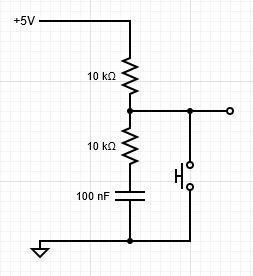
OK, here's my second attempt. I feel that something close to this should be workable:

The discharging time constant will be 0.8 ms, and the charging time constant will be 4 ms. The steady state values seen by the input pin will be either 5 V or 1 V (which should be sufficiently low to be read as LOW).
The maximum current draw will be 1 mA (on switch closure with a fully charged capacitor).
From my experience, a high current will cause pitting and arcing
The difference Jim is in the amount of energy involved.
Supose you have an ideal capacitor of 0.1uF charged to 5V
Q = CV = 0.5uC
E = 0.5QV = 1.25 uJ
Why not add a series resistor sufficiently large to delay the HIGH→LOW transition until all bounces have stopped.
The instant the contacts close (there will still be some contact resistance, line and capacitor resistance and inductance, so it does take a short time) the capacitor will discharge to near zero.
For the analysis we treat all components as "ideal" - it gets VERY complicated otherwise and inductance effects are small compared to the capacitance and resistance.
Basically, i've tested it extensively, it works, and as i say in the link, the only concern is if your wiring layout is so bad you get surge voltages elsewhere.
However if you are using a circuit that will be subject to EMI then there is no reason not to include a SMALL series resistor.
Like in your circuit, a 20k pull-up and a 47 ohm series resistor would limit the surge current to 0.1A and dramatically reduce transients.
That circuit is perfect but there is no reason to have different time constants for open and close. Why not make the 20K also 5K and make the capacitor bigger.
A user won't notice if there is a delay of 100ms or less when they push the button and something happens. So I think time constants up to 30ms would be OK and provide plenty of de-bouncing.
Rule of thumb for RC time constant: It takes about 3 time constants to get to within 95% of the final value
With how may different buttons and how may button presses?