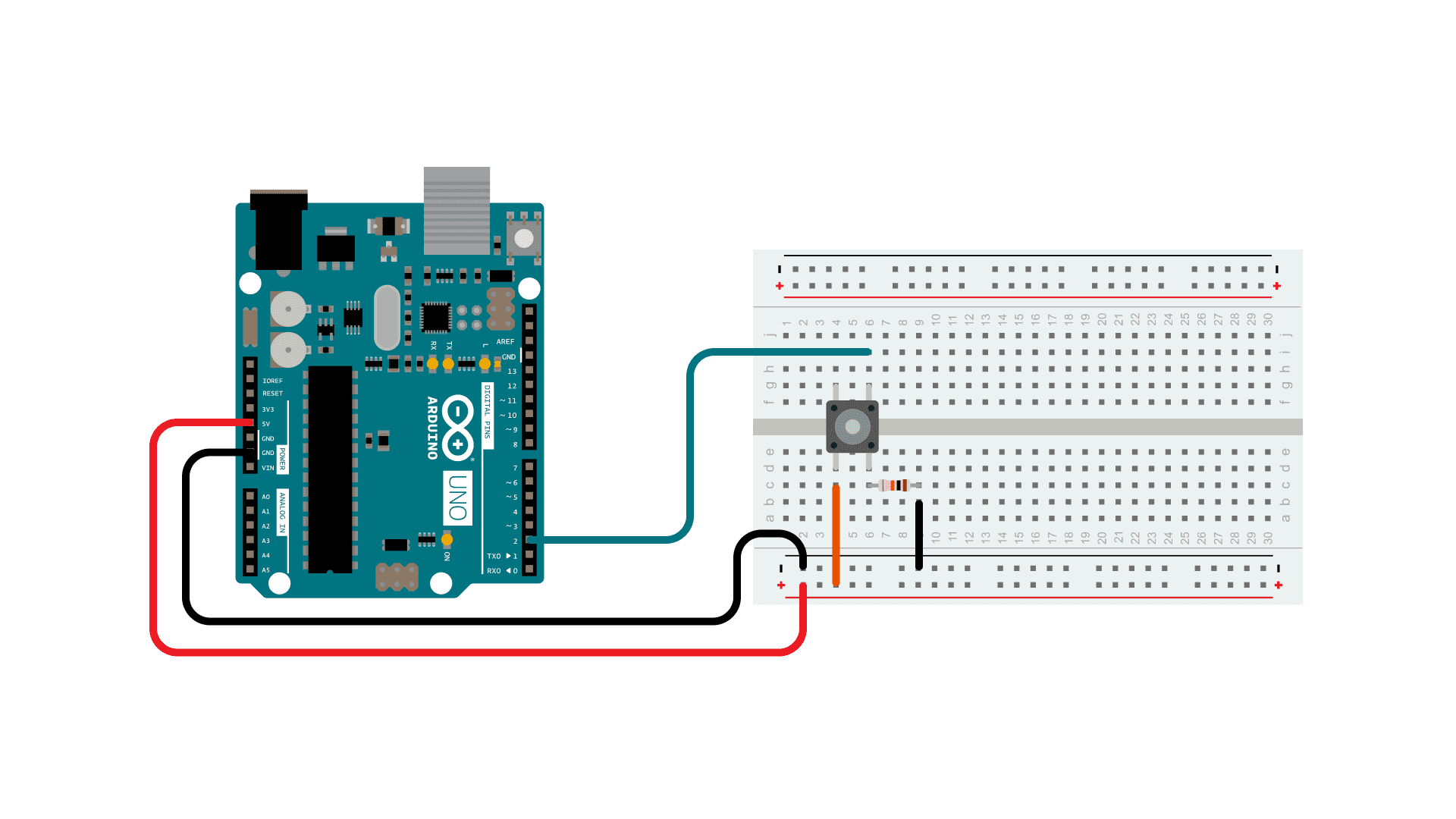
I want to create a project with 2 momentary buttons similar to the graphic.
Is it necessary to apply voltage? and why?
There are example on the internet with and without voltage.
If you set the pin mode to INPUT, you need to supply power. If you set the pin mode to INPUT_PULLUP, you do not need to supply power.
The issue with setting the pin mode to INPUT is that if there is no voltage applied to the digital pin when the switch is open (not pressed), then the state of the pin is undefined ("floating"), and may randomly be read as either HIGH or LOW. Thus, a so-called pull-down or pull-up resistor is used to ensure that the digital input pin is always a connected (via the resistor) to either ground or a HIGH voltage. Your diagram shows a pull-down resistor connected to ground.
thank you ! that make sense. Which method would be more stable?
In order to detect a digital input the pin must change state from HIGH to LOW or vice versa, hence the need for both positive (HIGH) and GND (LOW) connections to it
It is not clear how the button is wired in your illustration because it is impossible to determine which switch pins are connected when the button is pressed. I suggest that you rewire the circuit to use diagonally opposite connections to the button as this guarantees that you have wired across the switch contacts
Your circuit uses a pulldown resistor to hold the input LOW until the button is pressed to take it HIGH which you can use to detect a button press
To reduce the wiring and eliminate the external resistor you can use INPUT_PULLUP in pinState() for the input pin which will activate the built in pullup resistor which keeps the pin normally HIGH. Wire the button to take the pin LOW when the button is pressed and detect LOW as a button press. This is the configuration that you have seen where there is not a positive connection
Using external power with pull-down or pull-up resistors, or using the INPUT_PULLUP method (with no external power) are both equally "stable".
When using the INPUT_PULLUP method (or an external pull-up resistor), a button-press changes the digital input from HIGH to LOW, which may be counterintuitive for a person, but is very easy to deal with in the code.
Yes, you need voltage. On an Uno, a high or logic 1 is about 5V and low or logic 0 about 0V.
With a regular single-pole switch there are 2 ways to wire it:
You can use a "pull-up" resistor connected to 5V to pull the input high, then wire the switch to ground so that when the button is pushed, the resistor is "overpowered" and the input is forced low (and current flows through the resistor).
There is an internal pull-up resistor that can be enabled in software so you don't need to add an external resistor. So you don't need external voltage to the switch. It can come from the internal pull-up resistor.
In general, pull-ups are more common and the built-in pull-up makes it a lot more convenient.
Or, you can wire the switch to 5V and use a pull-down resistor connected to ground.
Obviously the logic is opposite with each method. If you have a pull-up resistor it reads 1 until the button is pushed and it reads 0. And of course, the software can work either way... i.e. You could make an LED come-on when the input is high or when the input is low.
...in pinMode(), right? Or is there a pinState() function, too?
Could you explain exactly what you mean by stable?
Is there a particular application you have in mind?
Stable would indicated when I press the button once the loop recognizes and input.
This is for a timer.
In that case stability has nothing to do with whether you use internal or external resistor. You need to debounce the button press in your software.
https://docs.arduino.cc/built-in-examples/digital/Debounce/
This is the one you show in your example.
The best way to connect a switch or button is to use a pull-up - either ineternal or a real external pull-up.
Making any connection between an arduino input and the positive supply is hazardous, especially if there is no protection resistor.
You can avoid the need for software debouncing very simply by connecting a small capacitor across the switch as shown here
Yes, pinMode()
My mistake !
Take a look at the built in examples and the forum discussion about the button example:
And for multiple buttons, I modified the Examples/Digital/02.toneKeyboard code to work with pinMode(pin, INPUT_PULLUP) and digitalRead(pin):
Did you understand what I said about debouncing and the resistors?
Jim-p , i do understand debouching. I am wondering if this is a better solution: https://docs.arduino.cc/built-in-examples/digital/InputPullupSerial/
"Better" in what sense? It requires fewer components, but it will have require just as much debouncing as the circuits that use external pull-up or pull-down resistors.
So using 5V helps eliminate debouching ?
No. There will be just as much bounce if your switch is powered by 5V as if it is not.
But by your questions, I'm starting to doubt your earlier assertion:
I strongly recommend that you read the following tutorial on switches from start to finish. It should clear up a lot of confusion for you if you read it carefully:
You got it "grb" thanks. I did not fully understand! For my purpose a software solution will be applicable. From what I read there are two solution: hardware and software
it will take me a while to comprehend: Gammon Forum : Electronics : Microprocessors : Switches tutorial
You can avoid the need for software debouncing very simply by connecting a small capacitor across the switch
why add unnecessary complication to your code?