Calibrating an accelerometer using the Magneto software

Hello,

I am calibrating my accelerometer sensor by following a tutorial by a person named Merlin from sailboatintruments1. And so far it's doing a great job at showing me how far I am off from a calibrated sensor.

I have a couple of questions:

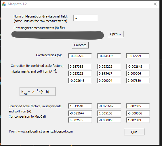
  1. The software doesn't provide what is the x, y, or z axis and I am assuming its respectively x, y, and z from left to right?

  2. I see the formula to use to calibrate my raw values but I don't know how to implement if I have a scale factor in the form of a matrix, or at least it looks like a scale factor matrix.

  3. Is it the "Correction for combined scale factors, ..." or is it the "Combined scale factors, ..." matrix that I use for calibrating? I assume the "Correction for Combined scale factors, ..." because it is represented as the variable A^-1 .

  1. Any axis pointing directly up will report the acceleration due to gravity as a large positive number. Use that to decide which is x, y, or z.

  2. Use the first matrix for the correction. The code could be similar to the following:

// accelerometer correction factors from Magneto
float B[3]
{   79.60,  -18.56,  383.31};

float Ainv[3][3]
{ {  1.00847,  0.00470, -0.00428},
  {  0.00470,  1.00846, -0.00328},
  { -0.00428, -0.00328,  0.99559}
};


  //apply offsets (bias) and scale factors from Magneto
  for (i = 0; i < 3; i++) temp[i] = (Axyz[i] -B[i]);
  Axyz[0] = Ainv[0][0] * temp[0] + Ainv[0][1] * temp[1] + Ainv[0][2] * temp[2];
  Axyz[1] = Ainv[1][0] * temp[0] + Ainv[1][1] * temp[1] + Ainv[1][2] * temp[2];
  Axyz[2] = Ainv[2][0] * temp[0] + Ainv[2][1] * temp[1] + Ainv[2][2] * temp[2];
1 Like

I am now about to start trying this calibration out my PCB that I designed the accelerometer onto but after loading my main program onto my board I am reading -0.00 for all axis values.

I am essentially using the same program I was using with the Spark Fun LSM6DSO Breakout board. and that was working good.

I probed my SPI lines on my PCB and as expected CS, SCK, and MOSI are all working but the MISO line has no signal.

There is a portion of the program that begins the SPI and it actually says that it could not connect to the IMU sensor.

I do have other sensors such as a Display and Bluetooth that are on the same SPI bus. I plan to use different chip select pins though and the program I am running doesn't initialize or talk to those sensors, only to the accelerometer.

Below are snippets of my schematic and the code I was using to test the accelerometer on my PCB.

I am in need of some help.


/*
    References:
        - Github: https://github.com/michaelwro/accelerometer-calibration
        - Arduino Forum: https://forum.arduino.cc/t/calibrating-an-accelerometer-using-the-magneto-software/1321286
*/

#include <Streaming.h> // string calling
#include <SPI.h>       // serial communication
#include <SparkFunLSM6DSO.h>

unsigned long timeThen = 0;
unsigned long timeNow = 0;
unsigned long timeRead = 500;
float ax, ay, az;

boolean start = false;

LSM6DSO myIMU; // Default constructor is I2C, addr 0x6B

void setup()
{
    Serial.begin(115200);
    delay(500);
    SPI.begin();
    delay(10000);

    // SPI settings for the GYRO/ACCEL IMU
    if (myIMU.beginSPI(24, 10000000, SPI))
    {
        Serial.println("Ready.");
        delay(2000);
    }
    else
    {
        Serial.println("Could not connect to IMU.");
        Serial.println("Freezing");
        delay(2000);
    }

    if (myIMU.initialize(BASIC_SETTINGS))
    {
        Serial.println("Loaded Settings.");
        delay(2000);
    }

    timeNow = 0;
    timeThen = 0;
    ax = 0.0f;
    ay = 0.0f;
    az = 0.0f;
}

void loop()
{
    timeNow = millis();

    /* ACCELEROMETER */
    if (timeNow - timeThen >= timeRead)
    {
        ax = myIMU.readFloatAccelX(); // units are in G's where 1G = 9.81m/sec^2
        ay = myIMU.readFloatAccelY();
        az = myIMU.readFloatAccelZ();

        Serial << ax << " " << ay << " " << az << endl;
        float pitch = atan2(ay, sqrt(ax * ax + az * az)) * 180.0 / PI; // rotation on the x-axis
        float roll = atan2(-ax, az) * 180.0 / PI;                      // rotation on the y-axis
        Serial << "Pitch: " << pitch << "°" << "   " << "Roll: " << roll << "°" << endl;
        Serial << " " << endl;

        timeThen = timeNow;
    }
}

So digging a bit more into this I see in the code where it fails. It fails to get the part ID of the IMU sensor.

  /* IMU SENSOR */
  if (myIMU.beginSPI(24, 10000000, SPI))
    Serial.println("Ready.");
  else
  {
    Serial.println("Could not connect to IMU.");
    Serial.println("Freezing");
  }

When I dig deeper into the Arduino Library of the LSM6DS0 sensor, it is not reading the correct Part ID. I am supposed to get 0x6C but instead I was getting 0xFF.

status_t LSM6DSOCore::beginSPICore(uint8_t csPin, uint32_t spiPortSpeed, SPIClass &spiPort){

  commInterface = SPI_MODE;
  _spiPort = &spiPort; 
  chipSelectPin = csPin; 

#ifdef __AVR__
    mySpiSettings = SPISettings(spiPortSpeed, MSBFIRST, SPI_MODE1);
#endif
		// MODE0 for Teensy 3.1 operation
#ifdef __MK20DX256__
    mySpiSettings = SPISettings(spiPortSpeed, MSBFIRST, SPI_MODE0);
#endif
		
#ifdef ESP32
    mySpiSettings = SPISettings(spiPortSpeed, SPI_MSBFIRST, SPI_MODE0);
#endif

  pinMode(chipSelectPin, OUTPUT);
  digitalWrite(chipSelectPin, HIGH);

	uint8_t partID;
	readRegister(&partID, WHO_AM_I_REG);
	if( partID != 0x6C )
		return IMU_HW_ERROR;
  else
    return IMU_SUCCESS;
}

I decided to take off the Bluetooth module that snapped into my PCB and check the SPI signal wires with an oscilloscope again. Now CS, MOSI, MISO, and SCK all have signals.

Although my remaining issue is till present, I am still not getting any readings from the IMU sensor and the Part ID is still wrong. Now I get a PART ID of 0.

Any suggestions?

I was able to solve the failure to connect to the IMU. The pins_arduino.h file had assigned the wrong pin to the MISO line.

This topic was automatically closed 180 days after the last reply. New replies are no longer allowed.