recommend you get a user manual or a schematic which shows the pinouts of the various connectors
first time we have heard about a ballast resistor and op-to isolator - is this a new requirement?
it would be a good idea to give more details of the project
Isn't updating the display every 0.9375s a bit slow for a tachometer?
I would have thought that having several updates per second would be more preferable.
You can get a frequency measurement quicker if instead of counting pulses for a given time, that you measure the period of the waveform and calculate the frequency from:
frequency = 1 / period
Given that RPM is rotations per minute, technically your counting period should be one full minute. There really aren't many rotations happening during 1 second, and counting the number of ignitions per second (for a V8) gives you a resolution of 15 RPM. My primary use of this tach is for diagnostics - to set idle RPM, and also make a graph of the distributor advance as a function of RPM. If I can package it up and ruggedize it sufficiently, I might incorporate it into a cabin display system.
I had thought about the 1-second update period, my way to solve that would still be to perform counting over the .93 or 1 second intervals but have 4 separate counters operating 1/4 second apart. The displayed RPM would still be delayed by 1 second, but there would be 4 updates per second,not just one.
The idea of measuring the time between any two ignition pulses would require very reliable high-resolution time measurements, and there is likely to be a lot of variation in the measurements for a carburated engine using mechanical points/condenser ignition, the numeric display of RPM in that case would be visually irritating.
But I see it is not a crystal for the actual processor clock.
The data sheet says:-
The Nano R4 features an external 16 MHz crystal oscillator that improve considerably the accuracy of the RTC and other sub-clock dependent peripherals.
test using a simple running average when frequency input 200Hz is varying randomly by 10%, e.g. 200Hz
shift 9 period = 5000uSec frequency = 200.000Hz
shift 9 period = 4650uSec frequency = 215.054Hz
shift 9 period = 4550uSec frequency = 219.780Hz
shift 9 period = 5150uSec frequency = 194.175Hz
shift 9 period = 4950uSec frequency = 202.020Hz
shift 9 period = 4850uSec frequency = 206.186Hz
shift 9 period = 4650uSec frequency = 215.054Hz
shift 9 period = 5100uSec frequency = 196.078Hz
shift 9 period = 5350uSec frequency = 186.916Hz
shift 9 period = 5400uSec frequency = 185.185Hz
shift 9 period = 5400uSec frequency = 185.185Hz
shift 9 period = 4650uSec frequency = 215.054Hz
shift 9 period = 5100uSec frequency = 196.078Hz
shift 9 period = 4700uSec frequency = 212.766Hz
shift 9 period = 4700uSec frequency = 212.766Hz
shift 9 period = 4900uSec frequency = 204.082Hz
shift 9 period = 5100uSec frequency = 196.078Hz
shift 9 period = 5050uSec frequency = 198.020Hz
shift 9 period = 4750uSec frequency = 210.526Hz
shift 9 period = 5100uSec frequency = 196.078Hz
shift 9 period = 5400uSec frequency = 185.185Hz
shift 9 period = 4700uSec frequency = 212.766Hz
shift 9 period = 4600uSec frequency = 217.391Hz
shift 9 period = 4800uSec frequency = 208.333Hz
shift 9 period = 4650uSec frequency = 215.054Hz
shift 9 period = 5300uSec frequency = 188.679Hz
shift 9 period = 4750uSec frequency = 210.526Hz
shift 9 period = 5050uSec frequency = 198.020Hz
shift 9 period = 4900uSec frequency = 204.082Hz
shift 9 period = 4650uSec frequency = 215.054Hz
shift 9 period = 4650uSec frequency = 215.054Hz
shift 9 period = 5350uSec frequency = 186.916Hz
shift 9 period = 5250uSec frequency = 190.476Hz
shift 9 period = 4700uSec frequency = 212.766Hz
shift 9 period = 5200uSec frequency = 192.308Hz
shift 9 period = 4650uSec frequency = 215.054Hz
shift 9 period = 5300uSec frequency = 188.679Hz
shift 9 period = 5250uSec frequency = 190.476Hz
shift 9 period = 4650uSec frequency = 215.054Hz
shift 9 period = 4550uSec frequency = 219.780Hz
shift 9 period = 4750uSec frequency = 210.526Hz
shift 9 period = 4550uSec frequency = 219.780Hz
shift 9 period = 4850uSec frequency = 206.186Hz
shift 9 period = 5350uSec frequency = 186.916Hz
ESP32 code
// ESP32 - simple running average - measure pulse width and rising edge-to-edge time using timer1 pins 16 and 17

//  average = (Current_reading + average) / 2

// updated for Arduino ESP32 core 3.0 see
// https://docs.espressif.com/projects/arduino-esp32/en/latest/api/timer.html

// note using hw_timer_t or micros() give similar values
hw_timer_t *Timer1_Cfg = NULL;  // timer object

// pulse timing data
volatile uint64_t riseTime, period, width;
volatile uint64_t averageFreq = 0, frequency;
// rising edge interrupt calculate period uSec
void IRAM_ATTR rising() {
  uint64_t rise = timerReadMicros(Timer1_Cfg);
  period = rise - riseTime;
  riseTime = rise;
  frequency = 1000000ul / period;
  if (averageFreq == 0) averageFreq = frequency;    // initialize
  else
    averageFreq = (frequency + averageFreq) / 2;    // running average
}

// falling edge interrupt calculate pulse width uSec
void IRAM_ATTR falling() {
  width = timerReadMicros(Timer1_Cfg) - riseTime;
}

void setup() {
  Serial.begin(115200);
  delay(1000);
  Serial.printf("\n\nESP32 running average - measure pins 16 and 17 pulse information \n");
  //Timer1_Cfg = timerBegin(0, 80, true);           // API 2.x setup timer for 1uSec
  if ((Timer1_Cfg = timerBegin(10000000)) == NULL)  // API 3.0 setup timer for 1uSec
    Serial.println("timerBegin Failed!!");
  Serial.print("timerBegin() OK frequenmcy ");
  Serial.println(timerGetFrequency(Timer1_Cfg));
  //  setup interrput routines - connect signal to pins 16 and 17
  attachInterrupt(digitalPinToGPIONumber(16), rising, RISING);    // detect rising edge on pin 16
  attachInterrupt(digitalPinToGPIONumber(17), falling, FALLING);  // detect falling edge on pin 17
  Serial.println("displaying results");
}

void loop() {
  static unsigned long int timer = millis();
  // if .1 seconds have elapsed since last reading print results
  if (millis() - timer > 100) {
    static int i;
     timer += 100;
    //  Serial.printf("period %llduSec width = %llduSec  frequency %.2fHz\n",
    //                period, width, 1000000.0/period);
    // print current raw frequency and running average
    Serial.printf("%d %d %d\n", i++, (int)frequency, (int)averageFreq);
  }
}
The crystal will be used by all the peripheral timers etc - the processor will be using the internal at 48MHz for itself and the USB etc.
However, we have the code to change the clocks to do what we want - without the pesky business of having to solder in a crystal.
There is no such requirement, "technically" or not. If you are getting 60 ignitions per minute, then you can in principle estimate the rotational speed in as little as 1 second.
The minute interval in "per minute" is just a standard reference interval. Alternatively, rotational speeds can be measured and/or expressed in radians per second, cycles per second, degrees per year, etc.
The choice of units does not affect how the rotational speed is measured, and you can easily convert from one set of units to another after the measurement has already been made.
The RA4M1 has rather a lot of clocking options. The ARM processor is divided up into several independent modules, with clock/data synchronization as required.
The basic rule-of-thumb is that the USBFS module must remain on the 48MHz from the H0CO, the rest is up for grabs.
With the crystal fitted, all the peripheral timers etc should be driven by that so we should have much better timing-accuracy.
Which clock-source the main ICLK is derived from I am not sure yet, I need to dump the clock registers to see the settings.
Sorry to be vague, it's been a while since I have looked at this.
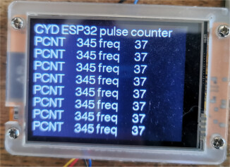
@horace I have your code (post #18) running on a CYD. I have a square wave going into GPIO-22, 50% duty cycle, frequency is 36.08 hz. The CYD is displaying X freq Y where X ranges from 480 to 490 and Y ranges from 50 to 52. I calculate that this signal would be 540 - 550 RPM.
If I change the frequency to about 123 or 124, X ranges from 1600 to 1680, and y ranges from 170 to 179. This should read 1850 rpm.
a input of 123Hz gives PCNT 1152 and frequency 123
However, the PCNT module is good for measuring stable pulse inputs over long periods but I understand you are attempting to measure RPM signals for a mechanical switch
the technique of counting rising/falling edge interrupts of post 31 would probably be more suitable and using a smoothing technique on the results
e.g. inputting 123Hz gives output
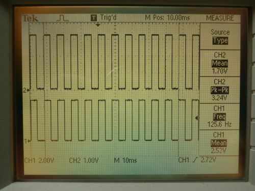
For testing I am using a signal generator. It creates a 5V signal, I convert it to 3.3v. Both signals are on this scope screen. Here the scope measures the frequency to be 125.6 hz. Using the cursors, I measure the frequency to be 126.3 hz.
Here is the screen of the CYD. Is is printing a new line every 10 seconds - can that time be reduced? And why is there so much variation in the numbers?
For my application, I am getting 8 pulses for every 2 rotations of the crank shaft, or 4 pulses per revolution. So multiplying the frequency by 15 would give me the RPM, which in this case should be 1890 (+/- 5).
OK, I have this running. The updating is too fast, and the number being displayed is not stable. It shows numbers like 125 and sometimes over 200. Lots of different values flipping around. Can the code be changed to count over a 1 second time, and multipy the result by 16 and display it as RPM and not HZ ?