Can an arduino perform this task (pulse counter) ?

I have a project in mind and wanted to know if it can be done with an arduino.

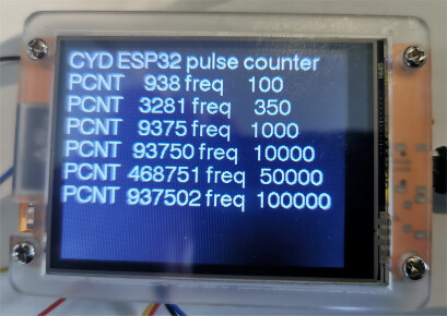
I have a digital logic signal to be analyzed. It can either be active-high or active low. It is essentially a pulse, and I want to count how many pulses happen during a very specific period of time - which is 0.9375 seconds (so just under 1 second). The pulse frequency will range from 30 to 350 hz. I can make the pulse to be a specific duration, likely this will be 1.5 milli-seconds.

So I expect there will be anywhere from 30 to 350 counts during the time interval 0.9375 seconds. The arduino would presumably be able to check the state of an I/O pin where the pulse is coming in and detect the transition from low to high and increment a 16-bit binary variable holding the count value.

Once the .9375 second time interval has happened, counting stops and the binary count value is multiplied by 16 (left-shift 4 bits).

The resulting value is anticipated to be in the range of 450 to 5000 (an integer value). I want this value to be displayed by a 4-digit LED display.

The count value will then be reset to zero and the entire process will begin again.

The key here I guess is - can the arduino measure the counting interval of 0.9375 seconds accurately? Or, based on it's internal timers, is some other time interval more accurate? 1.0 seconds perhaps? The time interval of 0.9375 is chosen so that the binary multiplication by 16 can be accomplished with a 4-bit left shift, which should be very fast to perform.

And does it have the temporal resolution to check the state of an input pin that might be in an active state for as little as 1.5 ms ?

How exact? I can think of a couple of methods.

  1. use millis() and the blink without delay style code for your event period, and use an interrupt-based counter to count only during the event period, capturing the new count at the end. Will be accurate to the nearest millisecond most of the time, but will occasionally slip one IIRC.

  2. use a hardware timer an an external logic device to gate the input signal, so that you control when the interrupt routine is triggered. That gives you better control over the event period, but you also need to see the gate signal, so that you know when the period is complete and a count should be displayed. This would be better, I think.

Questions

  • why are you concerned about the multiplication time? It can be done during the next counting period, as can the display.
  • is there a need to count continuously, or can you not count for some time while calculating and displaying the result

Others will have more elegant solutions, no doubt.

2 Likes
  • Assumption is there is no high frequency glitching. :thinking:

  • As @camsysca suggested, but micros() may be appropriate.
    Sample the GPIO every 100us.
    The rest of the code needs to be non blocking.

  • Perhaps use an interrupt pin, enable the interrupt, increment variable on rising/falling edge, after 1 second (0.9375 seconds), disable interrupt, do your math stuff, display number, start again . . .

1 Like

Although the target MCU architecture was not presented, I will share some information about the UNO R4, which I have used, for idea 2. mentioned by @camsysca.

The UNO R4 timer "AGT" has an "event counter mode" that can count the rising or falling edge of an external pulse.

Since it is a 16-bit counter, it should be able to count from 30Hz to 350Hz.

Also, since the base clock of the AGT is 32.768KHz, even if the division ratio is 1, it can measure 0.9375 seconds by counting 30720 times. In other words, by using two AGTs, it is possible to stop counting the external pulse at 0.9375 seconds.

However, as @camsysca pointed out, the UNO R4 does not have a built-in crystal oscillator, so there may be problems with accuracy.

Anyway, there is probably no appropriate library, so you will need to refer to the hardware manual and program using registers.

The following header file should be useful, as it defines the registers and their addresses that can be used with the UNO R4.

Good luck!

You may want to consider other more powerful boards.

I would have thought that you need some way to synchronise the starting point, like on the first pulse detected. Otherwise the count will always be changing.

The counter/timers on an Arduino R3 can be directly triggered by an external input. I would use the timer with a 16 bit counter (can't remember off hand which one it is). All the information is in the chip's data sheet.

You may want to take a look at the Freq Count Library.

I expect there will be anywhere from 30 to 350 counts during the time interval 0.9375

Your frequency is a bit low for the recommended range of this library, but I think it is worth trying.

I think one or two of the ATmega328P's timers allow for the use of an external clock signal to increment the count. If you could set that up, then your pulses would be counted automatically.

You could also set up timer1, for example, in capture mode. Your pulse would capture the current timer count, but more important it would trigger an interrupt which could be used to increment the pulse count. But of course you could also do that on the D2 or D3 interrupt without using the timer at all.

Arduinos, based on ESP32 as well as generic ESP32 development boards, have a hardware to count pulses precisely up to 70Mhz : it is called PCNT.

1 Like

second @vvb333007 suggestion of using the ESP32 Pulse Counter (PCNT)
the document sates
Calculate periodic signal's frequency by counting the pulse numbers within a time slice

I have used PCNT in the past - will have look to see if I have suitable example code

I'd assign the pulse input as an interrupt, and increment the counter in the ISR. You can also handle "bounce" there if your pulse input may not be clean.

yes. With micros() or with one of the timers.
The accuracy of the millis() / micros function is governed by the clock in your Arduino board which is driven by either a crystal or ceramic resonator. A crystal has an accuracy of roughly +/- 50 parts per million (ppm) or so (some are more accurate some are less, but 50ppm is about right for a cheap crystal).

Running a background task which turn GPIO2 LOW and HIGH at maximum speed; running PCNT on it:

found this simple pulse counter using PCNT

// ESP32 pulse counter using PCNT unit
//
// https://docs.espressif.com/projects/esp-idf/en/stable/esp32/api-reference/peripherals/pcnt.html

#include "driver/pulse_cnt.h"
#include "driver/gpio.h"
#include "esp_err.h"  

#define EXAMPLE_PCNT_HIGH_LIMIT 20000
#define EXAMPLE_PCNT_LOW_LIMIT -100

#define PULSE_INPUT_PIN 16

pcnt_unit_config_t unit_config = {
  .low_limit = EXAMPLE_PCNT_LOW_LIMIT,
  .high_limit = EXAMPLE_PCNT_HIGH_LIMIT,
  .flags = {
    .accum_count = 1,
    // .en_step_notify_up=1,
    //.en_step_notify_down=0
  }
};
pcnt_unit_handle_t pcnt_unit = NULL;

pcnt_chan_config_t chan_config = {
  .edge_gpio_num = PULSE_INPUT_PIN,
  .level_gpio_num = -1,
};
pcnt_channel_handle_t pcnt_chan = NULL;

hw_timer_t *timer = NULL;

volatile int pulse_count=0, data=0;
void ARDUINO_ISR_ATTR onTimer() {
  static short int  counter=0;
  if (++counter<1000)return;
  counter=0;
  int temp;
   pcnt_unit_get_count(pcnt_unit, &temp);
   pulse_count=temp;
   data=1;
}
void setup(void) {
  Serial.begin(115200);
  delay(2000);
  Serial.println("\n\nESP32 pulse counter using PCNT unit");
  // Set timer frequency to 1MHz
  timer = timerBegin(1000000);

  // Attach onTimer function to our timer.
  timerAttachInterrupt(timer, &onTimer);

  // Set alarm to call onTimer function every second (value in microseconds).
  // Repeat the alarm (third parameter) with unlimited count = 0 (fourth parameter).
  timerAlarm(timer, 1000, true, 0);


  Serial.println("install pcnt unit");
  ESP_ERROR_CHECK(pcnt_new_unit(&unit_config, &pcnt_unit));
  Serial.println("install pcnt channels");
  ESP_ERROR_CHECK(pcnt_new_channel(pcnt_unit, &chan_config, &pcnt_chan));
  Serial.println("set edge and level actions for pcnt channels");
  ESP_ERROR_CHECK(pcnt_channel_set_edge_action(pcnt_chan, PCNT_CHANNEL_EDGE_ACTION_HOLD, PCNT_CHANNEL_EDGE_ACTION_INCREASE));
  Serial.println("add watch point");
  ESP_ERROR_CHECK(pcnt_unit_add_watch_point(pcnt_unit, EXAMPLE_PCNT_HIGH_LIMIT));

  Serial.println("enable pcnt unit");
  ESP_ERROR_CHECK(pcnt_unit_enable(pcnt_unit));
  Serial.println("clear pcnt unit");
  ESP_ERROR_CHECK(pcnt_unit_clear_count(pcnt_unit));
  Serial.println("start pcnt unit");
  ESP_ERROR_CHECK(pcnt_unit_start(pcnt_unit));
}

// display pulse count every second
void loop() {
  if (data==0)return;
    ESP_ERROR_CHECK(pcnt_unit_clear_count(pcnt_unit));
    Serial.printf("Pulse count: %d\n", pulse_count);
    data=0;

}

some results counting for one second

10Hz square wave
Pulse count: 10
Pulse count: 10
Pulse count: 10
Pulse count: 10
Pulse count: 10
Pulse count: 10
Pulse count: 10
Pulse count: 10
Pulse count: 10
Pulse count: 10

100Hz
Pulse count: 100
Pulse count: 100
Pulse count: 100
Pulse count: 100
Pulse count: 100
Pulse count: 100
Pulse count: 100
Pulse count: 100

1KHz square wave
Pulse count: 1000
Pulse count: 1000
Pulse count: 1000
Pulse count: 1000
Pulse count: 1000
Pulse count: 1000
Pulse count: 1000
Pulse count: 1000
Pulse count: 1000
Pulse count: 1000
Pulse count: 1000
Pulse count: 1000
Pulse count: 1000
Pulse count: 1000

10KHz
Pulse count: 10000
Pulse count: 10001
Pulse count: 10000
Pulse count: 10000
Pulse count: 10001
Pulse count: 10000
Pulse count: 10000
Pulse count: 10001
Pulse count: 10000

100KHz
Pulse count: 100003
Pulse count: 100003
Pulse count: 100003
Pulse count: 100004
Pulse count: 100003
Pulse count: 100004
Pulse count: 100003
Pulse count: 100003
Pulse count: 100003

the above uses a timer interrupt every second
could well be a better way of timing the count period

update: ESP32 pulse counter using PCNT unit - using esp_timer callback

// ESP32 pulse counter using PCNT unit - using esp_timer callback
//
// https://docs.espressif.com/projects/esp-idf/en/stable/esp32/api-reference/peripherals/pcnt.html
// https://circuitlabs.net/pulse-counter-pcnt-module/

#include "driver/pulse_cnt.h"
#include "driver/gpio.h"
#include "esp_err.h"

#define EXAMPLE_PCNT_HIGH_LIMIT 20000
#define EXAMPLE_PCNT_LOW_LIMIT -100
#define GATE_TIME_MS 1000  // 1 second gate time


#define PULSE_INPUT_PIN 16

pcnt_unit_config_t unit_config = {
  .low_limit = EXAMPLE_PCNT_LOW_LIMIT,
  .high_limit = EXAMPLE_PCNT_HIGH_LIMIT,
  .flags = {
    .accum_count = 1,
    // .en_step_notify_up=1,
    //.en_step_notify_down=0
  }
};
pcnt_unit_handle_t pcnt_unit = NULL;

pcnt_chan_config_t chan_config = {
  .edge_gpio_num = PULSE_INPUT_PIN,
  .level_gpio_num = -1,
};
pcnt_channel_handle_t pcnt_chan = NULL;

hw_timer_t *timer = NULL;

volatile int data = 0;
volatile float frequency;
// esp_timer callback to read count and calculate frequency
static void IRAM_ATTR freq_measurement_timer_callback(void *arg) {
  int pulse_count;
  if (pcnt_unit) {  // Ensure pcnt_unit is initialized
    // 1. Get the pulse count
    if (pcnt_unit_get_count(pcnt_unit, &pulse_count) == ESP_OK) {
      // 2. Calculate frequency
      // Since GATE_TIME_MS is in milliseconds, convert to seconds for Hz
      frequency = (float)pulse_count / (GATE_TIME_MS / 1000.0f);
      // ESP_DRAM_LOGI(TAG, "Pulses in %dms: %d, Frequency: %.2f Hz", GATE_TIME_MS, pulse_count, frequency);
      data = 1;   // indicate new data to be printed in loop()
      // 3. Clear the PCNT counter for the next interval
      pcnt_unit_clear_count(pcnt_unit);
    }
  }
}

void setup(void) {
  Serial.begin(115200);
  delay(2000);
  Serial.println("\n\nESP32 pulse counter using PCNT unit");
  Serial.println("install pcnt unit");
  ESP_ERROR_CHECK(pcnt_new_unit(&unit_config, &pcnt_unit));
  Serial.println("install pcnt channels");
  ESP_ERROR_CHECK(pcnt_new_channel(pcnt_unit, &chan_config, &pcnt_chan));
  Serial.println("set edge and level actions for pcnt channels");
  ESP_ERROR_CHECK(pcnt_channel_set_edge_action(pcnt_chan, PCNT_CHANNEL_EDGE_ACTION_HOLD, PCNT_CHANNEL_EDGE_ACTION_INCREASE));
  Serial.println("add watch point");
  ESP_ERROR_CHECK(pcnt_unit_add_watch_point(pcnt_unit, EXAMPLE_PCNT_HIGH_LIMIT));

  Serial.println("enable pcnt unit");
  ESP_ERROR_CHECK(pcnt_unit_enable(pcnt_unit));
  Serial.println("clear pcnt unit");
  ESP_ERROR_CHECK(pcnt_unit_clear_count(pcnt_unit));
  Serial.println("start pcnt unit");
  ESP_ERROR_CHECK(pcnt_unit_start(pcnt_unit));
  Serial.println("PCNT frequency measurement started");

  // Configure and start esp_timer for periodic frequency calculation
  const esp_timer_create_args_t periodic_timer_args = {
    .callback = &freq_measurement_timer_callback,
    .name = "freq_measure_timer"
  };
  esp_timer_handle_t periodic_timer;
  ESP_ERROR_CHECK(esp_timer_create(&periodic_timer_args, &periodic_timer));
  // Start the timer in periodic mode, timeout in microseconds
  ESP_ERROR_CHECK(esp_timer_start_periodic(periodic_timer, GATE_TIME_MS * 1000));
  ESP_LOGI(TAG, "esp_timer started for periodic frequency updates (%d ms interval)", GATE_TIME_MS);
}

// display pulse count every second
void loop() {
  if (data == 0) return;
  Serial.printf("frequency: %f\n", frequency);
  data = 0;
}

results

frequency: 10.000000

100Hz
frequency: 100.000000

1KHz square wave
frequency: 1000.000000
frequency: 1001.000000
frequency: 1000.000000

10KHz
frequency: 10000.000000
frequency: 10001.000000
frequency: 10000.000000
frequency: 10001.000000
frequency: 10000.000000
frequency: 10001.000000
frequency: 10000.000000
frequency: 10001.000000
frequency: 10000.000000

100KHz
frequency: 100003.000000
frequency: 100004.000000
frequency: 100003.000000
frequency: 100004.000000
frequency: 100003.000000
frequency: 100004.000000
frequency: 100003.000000
frequency: 100004.000000
frequency: 100003.000000

In my opinion there is no need to do this since you are waiting nearly a second before you have to calculate it again.

In my code below, I've turned a pin high,and had a delay of 100ms before turning it low again.
I did this for two reasons:

  1. To show that you don't need to be super quick.
  2. To generate a pulse that can easily be seen on an oscilloscope.

How accurate does the count need to be?
The CSTCE16MOV53-R0 ceramic resonator used in many Arduinos has a frequency tolerance of ±0.5%.
This means that the count can be out by ±0.5%, which is ±26 counts for a 350Hz input.

I'll go on to show you how you can do a calibration and remove this error (if you have an oscilloscope).


const byte inputPin = 2;
const byte outputPin = 12;

unsigned long previousMicros = 0;
const unsigned long interval = 937500;               // interval in  for counting pulses.

volatile unsigned long count = 0;
unsigned long pulses = 0;
unsigned long previousPulses = 0;
unsigned long pulseCount = 0;

void setup() {
  pinMode(inputPin, INPUT_PULLUP);
  pinMode(outputPin, OUTPUT);
  Serial.begin(115200);
  attachInterrupt(digitalPinToInterrupt(inputPin), countPulse, RISING);
}

void loop() {
  unsigned long currentMicros = micros();
  if (currentMicros - previousMicros >= interval) {

    noInterrupts();                                 // turn off interupts so count can't change while being read.
    pulses = count;                                 // get current value of count from the ISR.
    interrupts();                                   // turn interrupts back on.
    pulseCount = pulses - previousPulses;

    digitalWrite(outputPin, HIGH);                  // generate pulse for oscilloscope.
    delay(50);
    digitalWrite(outputPin, LOW);                   // generate pulse for oscilloscope.

    Serial.print(currentMicros - previousMicros);   // print results.
    Serial.print("µs  ");
    Serial.print(pulseCount);
    Serial.print("  ");
    Serial.println(pulseCount * 16);

    previousPulses = pulses;                        // set new value of 'previousPulses' for next time round.
    previousMicros = previousMicros + interval;     // update 'previousMicros' for timing.
  }
}

unsigned long countPulse() {
  count++;
}

Here are the results with a 320Hz input (chosen because it is towards the upper end of your frequency range, and it make the maths easier).

On the serial monitor, I've printed the sampling interval, the count during that time, and then 16 x that count.


My Arduino Uno's clock frequency isn't exactly 16MHz. It is slightly high.
You can tell this by the fact that the count isn't always 300 / 4800, and that the period of the yellow trace isn't 0.9375s as measured by the oscilloscope (it's 0.936415s).

You can 'calibrate' the system by multiplying the 937500 by (the required period / the measured period).

937500 * (937500 / 936415) = 938586

so (in my case) replace:

const unsigned long interval = 937500;

with:

const unsigned long interval = 938586;

When retested the count is now always 300 / 4800 and the oscilloscope measures the period as 0.9375s:

In case this hasn't been guessed yet, this project is 4-digit tachometer for an 8 cylinder engine. Counting pulses over a fixed time interval (I was thinking either .9375 or 1.0000 seconds). The interval would start upon the detection of the first rising edge of the pulse signal Yes it's always possible to have discrete logic create the interval signal, but then again with a little more discrete logic, a shift register and display driver you could make this entire thing out of discrete logic chips. Once the interval has ended it doesn't matter how much time it takes to compute the RPM (either multiply by 16 or 15 depending on the interval) and update the display, but I wouldn't want that to take more than say 100 ms because I want to quickly start a new measurement cycle.

I'm curious about the mention of ESP32 - because I've only used the ESP boards for Tasmota projects, so I have no idea how they integrate with arduino boards.

And I've actually never done anything with arduino before, so I'm looking at the various project boards and trying to make a decision based on what display shield is available for what arduino board. I'm thinking maybe the Arduino UNO R4 Minima is a good starting point here? I like the dot-matrix displays that are available, but I don't want to get bogged down hunting for libraries to make them work. On the other hand there doesn't seem to be a lot of choices when it comes to 4-digit 7-segment LED shields.

So maybe the bigger question here is, what hardware am I looking for (arduino board + display shield) ?

There are a number of Arduino tachometer projects, including this one:

https://www.youtube.com/watch?v=6QZMt4yyylU

if you require a display have a look at ESP32-Cheap-Yellow-Display
e.g. sampling pulses during 0.9375seconds

// CYD ESP32 pulse counter using PCNT unit - using esp_timer callback
//
// https://docs.espressif.com/projects/esp-idf/en/stable/esp32/api-reference/peripherals/pcnt.html
// https://circuitlabs.net/pulse-counter-pcnt-module/

// CYD TFT setup
#include <Arduino.h>
#include <TFT_eSPI.h>
#include <TFT_eSPI_Scroll.h>
#include <4bit.h>

TFT_eSPI tft;
TFT_eSPI_Scroll scroll;
// PCNT setup
#include "driver/pulse_cnt.h"
#include "driver/gpio.h"
#include "esp_err.h"

#define EXAMPLE_PCNT_HIGH_LIMIT 20000
#define EXAMPLE_PCNT_LOW_LIMIT -100
#define GATE_TIME_MS 9375  // gate time mSec


#define PULSE_INPUT_PIN 22

pcnt_unit_config_t unit_config = {
  .low_limit = EXAMPLE_PCNT_LOW_LIMIT,
  .high_limit = EXAMPLE_PCNT_HIGH_LIMIT,
  .flags = {
    .accum_count = 1,
    // .en_step_notify_up=1,
    //.en_step_notify_down=0
  }
};
pcnt_unit_handle_t pcnt_unit = NULL;

pcnt_chan_config_t chan_config = {
  .edge_gpio_num = PULSE_INPUT_PIN,
  .level_gpio_num = -1,
};
pcnt_channel_handle_t pcnt_chan = NULL;

hw_timer_t *timer = NULL;

volatile int data = 0, pulse_count;
;
volatile float frequency;
// esp_timer callback to read count and calculate frequency
static void IRAM_ATTR freq_measurement_timer_callback(void *arg) {
  int temp;
  if (pcnt_unit) {  // Ensure pcnt_unit is initialized
    // 1. Get the pulse count
    if (pcnt_unit_get_count(pcnt_unit, &temp) == ESP_OK) {
      pulse_count = temp;
      // 2. Calculate frequency
      // Since GATE_TIME_MS is in milliseconds, convert to seconds for Hz
      frequency = (float)pulse_count / (GATE_TIME_MS / 1000.0f);
      // ESP_DRAM_LOGI(TAG, "Pulses in %dms: %d, Frequency: %.2f Hz", GATE_TIME_MS, pulse_count, frequency);
      data = 1;  // indicate new data to be printed in loop()
      // 3. Clear the PCNT counter for the next interval
      pcnt_unit_clear_count(pcnt_unit);
    }
  }
}

void setup(void) {
  Serial.begin(115200);
  delay(2000);
  Serial.println("\n\nESP32 pulse counter using PCNT unit");
  Serial.println("install pcnt unit");
  ESP_ERROR_CHECK(pcnt_new_unit(&unit_config, &pcnt_unit));
  Serial.println("install pcnt channels");
  ESP_ERROR_CHECK(pcnt_new_channel(pcnt_unit, &chan_config, &pcnt_chan));
  Serial.println("set edge and level actions for pcnt channels");
  ESP_ERROR_CHECK(pcnt_channel_set_edge_action(pcnt_chan, PCNT_CHANNEL_EDGE_ACTION_HOLD, PCNT_CHANNEL_EDGE_ACTION_INCREASE));
  Serial.println("add watch point");
  ESP_ERROR_CHECK(pcnt_unit_add_watch_point(pcnt_unit, EXAMPLE_PCNT_HIGH_LIMIT));

  Serial.println("enable pcnt unit");
  ESP_ERROR_CHECK(pcnt_unit_enable(pcnt_unit));
  Serial.println("clear pcnt unit");
  ESP_ERROR_CHECK(pcnt_unit_clear_count(pcnt_unit));
  Serial.println("start pcnt unit");
  ESP_ERROR_CHECK(pcnt_unit_start(pcnt_unit));
  Serial.println("PCNT frequency measurement started");

  // Configure and start esp_timer for periodic frequency calculation
  const esp_timer_create_args_t periodic_timer_args = {
    .callback = &freq_measurement_timer_callback,
    .name = "freq_measure_timer"
  };
  esp_timer_handle_t periodic_timer;
  ESP_ERROR_CHECK(esp_timer_create(&periodic_timer_args, &periodic_timer));
  // Start the timer in periodic mode, timeout in microseconds
  ESP_ERROR_CHECK(esp_timer_start_periodic(periodic_timer, GATE_TIME_MS * 1000));
  ESP_LOGI(TAG, "esp_timer started for periodic frequency updates (%d ms interval)", GATE_TIME_MS);

  // setup CYD TFT display
  Serial.println("\ninitialise TFT");
  // Initializing tft_espi
  tft.init();
  tft.setRotation(1);
  tft.setTextSize(1);
  // Initializing the tft_espi_scroll int 1bit B/W
  if (scroll.init(&tft, 4) != NO_ERROR) {
    Serial.println("Failed... Reseting...");
    return;
  }
  /*String data;    // test output
  for (int i = 1; i <= 20; i++) {
    data = String("Count: ") + String(i);
    scroll.write(data);
    //must be called for longer loops otherwise watchdog will reset the mcu
    yield();
  }*/
  scroll.write("CYD ESP32 pulse counter");
  delay(1000);
}

// display pulse count every second
void loop() {
  if (data == 0) return;
  Serial.printf("pulse count %d frequency: %.1f\n", pulse_count, frequency);
  data = 0;
  //if (!Serial.available()) return;  // display if key hit - comment out if not required
  while (Serial.available()) Serial.read();
  tft.fillScreen(TFT_BLACK);
  char text[100] = { 0 };
  sprintf(text, "PCNT %7d freq %7d\n", pulse_count, (int)round(frequency));
  scroll.write(text);
}

as the CYD has an onboard ESP32 no need for external display with all the problem of interconnections etc

test with input 100Hz 350Hz 1KHz 10KHz 50KHz 100KHz

No it is not, because the Uno R4 uses a free running oscillator to drive it, so it is not stable nor is it precise. Even a ceramic resonator would be better. You can fit a crystal to one but it is a big big hack and with so little experience I would recommend you forget this. However if you want to see what is involved then @susan-parker can show you a link to where she did it.

1 Like

I ordered a couple of these: DIYmalls 2.8" ESP32-2432S028R (240 x 320) with acrylic case. The vendor has arduino IDE files available for download.

I think I can drive an LED from the voltage drop across the ballast resistor. I'm thinking of ordering a fiber-optic kit (IF-E10) from Digikey and use it as an opto-isolator.