Can anyone check my schematic? I have no idea what I'm doing, but it works :D

Hello. Can any pro check my project scheme before I put into a project box? I have a gut feeling there's something "wrong" with it. Yet it works.

The schematic:

What is this? I have a force sensor that needs to engage the relay and set a wiper position of the DS3502. The 2 potentiometers control the low and high limits of the force sensor. The display just shows the force that I'm pushing the sensor with and set limits.

I, by no means, have any knowledge. This is my first project and I literally don't know any best practices, or things like where to put additional resistors, capacitors, diodes etc.

Thanks in advance.

It's off topic but take a look at moving this diode. It should be in parallel and reversed.
image

Edit: IDK, I don't see anything wrong. Maybe post the code to make sure it's efficient???

1 Like

I don't think that it is off topic at all. The OP asked for a critique of the schematic.

To show what @apf1979 said:


NPN transistor relay driver with flyback diode.

A 0.1uF cap from each potentiometer (pot) wiper to ground will bypass noise to ground and help to stabilize the readings from the pots.

2 Likes

Agreed, also OP photos look like the transistor itself is (probably depending on the package, presumably since it "works") wired properly with emitter to ground but the circuit diagram shows it reversed. Need to fix the schematic.

2 Likes

Why are the 3.3V lines dotted?

Layer effect to differentiate it from 5v???

1 Like

Good eye, I missed that.

Wow, thank you, you are awesome!

  1. 3v3 dotted just to distinguish from the regular 5v solid line that I had removed in favor of +5v inlets.

  2. The diode on board is installed exactly as it is on schematic. I don't believe it's reversed, but, like I said, assume me an idiot.


  3. Did I also messed up the NPN transistor direction? I wired emitter to the relay:

  4. Do I need a capacitor near the force sensor?

The updated schematic looks like this:

And THANK YOU VERY MUCH!

A 0.1uF ceramic cap from the analog input to ground will bypass some noise to ground and help yo stabilize the signal from the FSR.

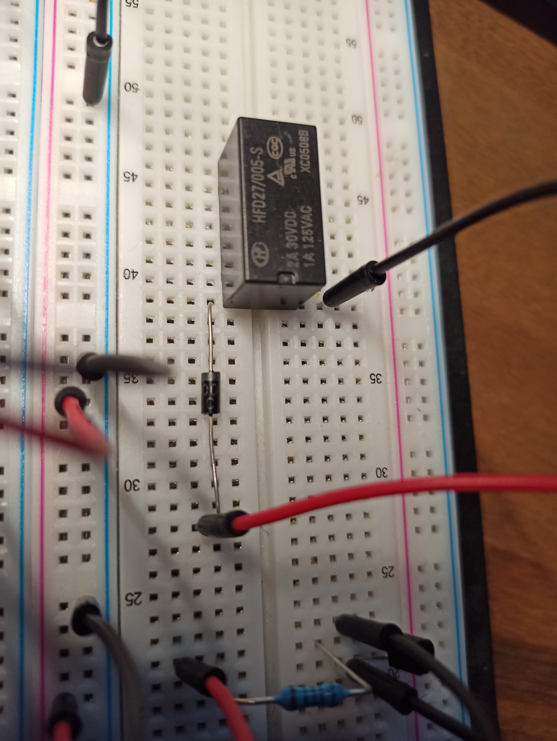
It is hard to tell from the phitos where wires go but it looks like the diode is still in series with the relay coil instead of in parallel like it should be.

Thanks, I will put a cap there. Does it matter if it should be before or after the resistor going to ground?

And yes indeed, the diode is in series. Just cathode is connected to the relay. I will fix it.

The cap goes across the 10K resistor. Input to ground.

Sorry, not following. Like that?

Right, I've fixed wiper capacitors placement:

Yes.

1 Like

That's not really information that belongs on the schematic.

Connections on schematics should be solid lines - dotted lines mean other things; eg, to indicate "ganged" components.

1 Like

Thanks, noted.

Thank you everyone for your help! Really appreciate it, everything is fixed and is about to get assembled!

This topic was automatically closed 180 days after the last reply. New replies are no longer allowed.