for the power source has been separated between the microcontroller and inductive proximity sensors, for the sensor using 24V.
Three-wire sensor with open-collector/open-drain output?
Connect GND to GND, output to ESP32 pin and set mode to INPUT_PULLUP.
What is "fhe sensor"?
sorry I missed the description of the info about the sensor used is “Inductive Proximity Sensor NPN NO 8mm LJ18A3-8-Z/BX”
So what is your problem?
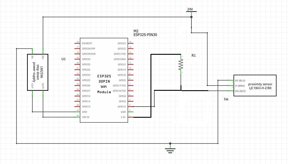
Add a schematic. One picture says more than 1000 words...
It seems open collector communication..
So you might try input pullup...
Please post a link to specs/data of sensor.
Does the spec sheet have example connection configurations?
Thanks.. Tom... ![]()
![]()
![]()
![]()
I'm a beginner in the use of inductive proximity sensors ![]()
![]()
well thanks, I'm trying to find
Well, thank you, can you explain how it works because it's my first time using an inductive proximity sensor ![]() ?
?
What else do you need to know? I answered the question that you asked.
I'm still a novice in cable design. for the components esp32, buck converter, 24V PSU and Inductive Proximity Sensor NPN-NO , from this picture is it correct from the cable ?

Not enough information. Please post a link to the product page for the exact switch you have.
For example, if it is this one, the sensor runs on 5V, which would make MUCH more sense for a 5V or 3.3V Arduino.
Operating Voltage: 6V - 36 V DC
Model: LJ18A3-8-Z/BX Proximity inductive NPN NO
Brand: LEFIRCKO
Type: 3 Wire Type (Brown, Blue, Black)
Output Current: 300mA (Max)
Frequency Response: DC: 0.5 kHz AC: 25 kHz
Detection Distance: 8mm±10%
Dimensions: ± M18 X 16.5 X 66 mm
Standard Detection Object: Iron 30 X 30 X 1 mm
Setting Distance: 0-7 mm
The sensor output appears to be open collector, so you need to connect only sensor GND and output to the Arduino, using pinMode(pin_number, INPUT_PULLUP);
Proximity is indicated by LOW on the Arduino input pin.
Remove 1.5 k resistor and connect 10 k resistor to vcc (3V3).
Is this different to the one I made before and can you explain how it works?
I'm still confused about what it is, when to use it and how it works. Anyway, thank you very much for the support of everyone who has given advice
Yes. Can't you tell from the schematic diagram?
An NPN open collector output is designed as an interface between two different logic level voltages. To use it, a pullup resistor is required from the sensor output to Arduino Vcc. That can be internal resistor (turned on with INPUT_PULLUP) or an external resistor to Arduino Vcc.
With a long sensor cable, you might want to use an external 1K resistor, to increase immunity to electrical interference.
okay, I'm starting to understand after studying it again. thanks for the advice and explanation
Anyway, thank you very much for the support of everyone who has provided advice and explanations