HI,
Can you draw a circuit diagram of what you describe in post #24?
Thanks.. Tom.... ![]()
![]()
![]()
![]()
HI,
Can you draw a circuit diagram of what you describe in post #24?
Thanks.. Tom.... ![]()
![]()
![]()
![]()
I showed you in post #31 how to do it.
However if you don't read 0V on the black wire without a pullup then the sensor is probably bad and I would not use it or connect it to the ESP
Hi,
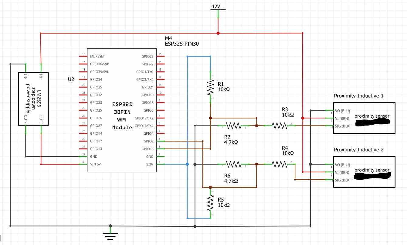
If your pullups R1 and R5 are connected to 3V3 you do not need any of the other resistors.
Tom.... ![]()
![]()
![]()
![]()
Hi, @hansmeow
Look at this circuit below.
Connect your like that.
Send us a picture of your project, when you have assembled it as in the diagram.
Connect the red lead to A, and move a sample passed the sensor, note the change in output of the sensor.
Connect the red lead to B, and move a sample passed the sensor, note the change in output of the sensor.
Then tell us what you get.
Tom.... ![]()
![]()
![]()
![]()
PS. This is very simple trouble shooting diagnostics.