As you have discovered, those two pins cannot be used as outputs of any kind. You can, use them as analogue inputs and use the value returned as a digital input with a single line of code to interpret the analogue value
Yes. They go directly to the ADC multiplexer. There are no digital buffers, so they cannot be used for digital I/O. The details are in the data sheet - but not particularly obvious.
Oh yeah! I was on a roll with a for-loop using the pins as 2-21 after I soldered it. I put a bunch of leds in a row. I first started with the d2-d13. Then I realized you just state the analogs as 14 onwards for analog pins.
I got that much worked out. Then I got really frustrated with 20 and 21. I thought I must have busted up on the soldering! But when I realized neither 20-21 was working, I kind of sussed it. I was going wild trying to work out if the jumper cables were busted or something.
The boards I got came with the headers. I wrote another post a while back about being worried about headers. I had to solder the spikey things onto it, the headers. I’m not so scared about it now. Just need a steady hand. Oh I found a really cool trick as well, just put the headers into a breadboard, and then solder them!
If you mean that you use pin numbers 14 onwards when using them as digital pins there is no need to do that. Just use the normal pin names, ie A0, A1, A2 etc
Breadboards are not designed to be heated.
What are you soldering relative to the breadboard
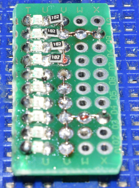
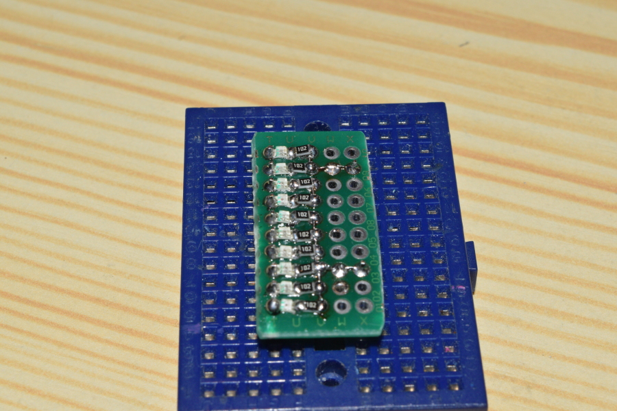
A female hdr is soldered to some sort of proto board. I will attach pictures of a few at the end.
One very cool board is a solderable version of a breadboard. That allows you to prototype in a standard breadboard then when working transfer it to a permanent board.
These are all amazon.ca, change the .ca to your country https://amz.cx/3WFI https://amz.cx/3WFJ https://amz.cx/3WFK https://amz.cx/3WFL https://amz.cx/3WFN
and lot's more, just do 'related' searches.
If you get a Nano with an ATmega328PB instead of an ATmega328P (some of the "clones" are doing this because the PB is cheaper), then a6 and a7 CAN be used as digital IO.
In the Nano Every A6 and A7 exist and can be addressed as digital pins 20 and 21. There are many boards with the name Nano having different microcontroller chips.
I have used breadboards as a header soldering jig before. However, I was not happy with it for several reasons:
The pins in the male headers can move vertically within the plastic spacer when you are pressing the header into the breadboard, or when removing the header prior to soldering if you need to reposition it.
The large metal strips inside that make the contacts act as heat sinks and so make soldering the headers more difficult, time consuming, and can result in lower quality joints.
The header can be held at an angle, which results in the header not being aligned perfectly perpendicular to the PCB after soldering.
A better solution is to get a few sheets of perfboard and use machine screws to mount them together in a stack. The boards often come with mounting holes at each corner, which makes it easy to do, but you can also easily drill holes for the screws if needed.
You can then use that as a base to hold headers, place the PCB over them, then solder.
The reason I recommend using a stack of multiple boards instead of only a single board is this ensures correct alignment of the headers. With only a single board, there is more freedom for the header to move angularly due to the fact that the pin is only constrained over the short distance of a single board's thickness. So it is possible to end up with headers that aren't perfectly perpendicular to the PCB after soldering when using a single layer of perfboard. Adding more layers of boards makes it so there is very little freedom for the header pin to be angled, ensuring perfect alignment when soldering.
It is best to use the perfboards that are pure substrate without plating:
However, the ones with only surface pads will work pretty much just as well (because there isn't much metal, and also won't be much contact between that metal and the pin), and are more commonly available:
I don't recommend using the plated through hole type of perfboard/protoboard for this purpose since the plating inside the holes will have significant contact with the header pin and so will also act as a heat sink:
Likewise, I would not recommend using stripboard, but the common non-plated through hole variant will work reasonably well if it is all you have on hand:


