Hi,
I am somewhat new to coding, and I am not asking for people to do my work for me. but an example may help or a link to some info.
I am trying to write code for a specific device. DS1867 - Maxim. The data sheet says it utilizes a 17 bit SPI form of communication (Based on representatives from Maxim/Dallas).
I have been attempting to communicate with this device and set specific bit values for the potentiometer using the SPI.h library included in arduino.
While i have had success, its not accurate the pots are not shifting to what i calculated or expect.. I have a feeling that it has to do with the 17th bit that i am missing. as far as i have researched it doesnt seem like the SPI.h library has a function to generate single bits along with the with a clock sync. only the 8 bit code when using SPI.Transfer().
I put the code I am using below. Right now its more of a simple proof of concept for me. So I only call out this function in my void Loop using the serial monitor as an input for now - a simple while loop that only moves on when I input an integer from 0-255... oh and just to make it more interesting I am using a cascading form of these pots. i only have 2 - but i am using the same values for all pots. Hopefully this isn't too messy and thank you for reading and/or help provided.
once i get this proof of concept down i can move on with the rest of my code.
Current Set up DIGITAL
Pin 13 = SCLK = CLK
Pin 12 = MISO = Not USED
Pin 11 = MOSI = DQ
Pin 10 = RESET = RST
void loop() {
Serial.println("Enter a Value between 1-255");
  Serial.println("");
  //wait for user input
  while (Serial.available() == 0) {

  }

  int potValue = Serial.parseInt();
  Serial.println("your value:");
  Serial.println(potValue);
  digitalPotWrite(potValue, potValue);

}

void digitalPotWrite(int POT0, int POT1) {
  // take the reset pin high to start communications.
  SPI.beginTransaction(SPISettings(1000, MSBFIRST, SPI_MODE1));
  digitalWrite(reset, HIGH);
  //delay(10);
  // send in the POT0 first and POT1 via SPI:

  SPI.transfer(POT0);
  SPI.transfer(POT1);
 // SPI.transfer(POT0);
  //SPI.transfer(POT1);
  digitalWrite(reset, LOW);
  //delay(10);
  // take the reset pin high to end communication:
  SPI.endTransaction();
}
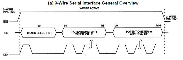
The communications protocol for the DS1867 is clearly described in the data sheet, and it is not difficult to "bit bang". Just use three digital pins for /RST, CLK and DQ, setting the latter two high/low in a loop, to transmit the data. Obey the timing restrictions (Tcc, Tch Tdc, Tcdh, etc.) given in the data sheet, which is not hard to do, since there is no maximum.
This is a form of the SSI interface, and an internet search will find Arduino examples.
Something similar to this will work:
digitalWrite(NRST, 1); //nRST high
digitalWrite(DQ, SSB);  //set stack select bit
digitalWrite(CLK, 1);
digitalWrite(CLK, 0);  //transmit it

unsigned int data = (potval0<<8) | potval1;  //two 8 bit pot values
for (int i=0; i<16; i++) {
digitalWrite(DQ, data&1); //set up low bit of data
digitalWrite(CLK, 1);
digitalWrite(CLK, 0);  //transmit it
data = data>>1;  //next bit to send
}
digitalWrite(NRST, 0);  //deactivate interface
I think you can write in chunks of 8 bits, with the data left aligned. The contents of the shift registers are transferred to the wiper registers when /RST goes low.
I would "manually" send the first bit and then use SPI for the pot values. By that I mean drive the CLK and DATA lines with the right pattern (as shown in the data sheet).
I saw some info on Bit Banging, and I was trying to understand the timing needed for it to work simultaneously and synchronize with the clock.
Sorry for asking this question - but I wondered what data&1 means?
Anyways, i looked at the output using this code and set it up. and it looks surprisingly a lot better than the SPI.transfer function. Everything is in surprisingly better synchronization. which is amazing!
Last thing i wanted to ask - the clock frequency. I see that this operates around 85kHz based on my measurements - any ideas to modulate this? I suppose i could use delays. I will play around with it and see what happens.
Although i see that this is sending out the bit in reverse?
For instance = i want to send bit 104. the original data would send out a binary number of 01101000.
with this code i see it sends it out as 00010110 instead.
but thank you for the example! this is extremely helpful. I will see what i can do to mess around with it and hopefully get a better understanding!
You got it wrong. The datasheet talks about using a 17-bit shift register. There is no talk about SPI there at all, only about a protocol similar to SPI.
To operate this potentiometer, you can use the Arduino shiftout() operation. Since it works with bytes - that is, chunks of 8 bits - send three bytes, two are complete, and the third has only one bit, and the rest are zeros
Thanks! Apologies, i saw a post from an applications engineer on these that claimed we could talk to it via SPI, but it could have been the previous model without the 17th bit added in. Thank you for the response.
Arduino shiftout() operation? I will look into it thank you for the suggestion!
Right seems like the way to go here. jremington suggested using Bit Banging. it seems to work similar to how you suggested "Manually" forcing the bit out by setting all the pins as outputs and cycling through a for loop with an extra bit cycle for that 17th bit.
I see, I was just looking at that.
so your code takes the integer value potVal0 and shifts it 8 bits and then joins value with potVal1 into data.
Then using the For loop you output each bit value one at a time using the bitwise & to return a low bit.
then the data >>1 continues to shift the 16bit to the right . forcing out the next bit value. on digital write.
thats really cool. however, i still have the issue of the bits coming out in the wrong order. I will shift around some things and see what i can do.
For instance = i want to send bit 104. the original data would send out a binary number of 01101000.
with this code i see it sends it out as 00010110 instead.
Correction: I misread the data sheet. "Bit 1" in the data stream is pot1 MSB, not LSB.
Revised code:
digitalWrite(NRST, 1); //nRST high
digitalWrite(DQ, SSB);  //set stack select bit
digitalWrite(CLK, 1);
digitalWrite(CLK, 0);  //transmit it

unsigned int data = (potval1<<8) | potval0;  //two 8 bit pot values
for (int i=0; i<16; i++) {
digitalWrite(DQ, !!(data&0x8000)); //set up MSB data (!! converts any non-zero value to 1)
digitalWrite(CLK, 1);
digitalWrite(CLK, 0);  //transmit it
data = data<<1;  //next bit to send
}
digitalWrite(NRST, 0);  //deactivate interface
Right! Sorry I wasn't sure on the meaning of MSB and LSB. but thats what i meant. MSB First type device.
i do have the device with me and i am using it as a voltage divider to correlate the bit value based on my calculations and i am monitoring the output DQ, ClK, and RST using an o.scope.
This looks to output the correct order now! just missing the second half of the bit values for some reason? I can see the clock is working, outputting 17 cycles and the reset is going from H to L in the given time. However, I only see the output of potVal0.
As an example of the problem potVal1 = 170 (10101010) and potVal0 = 104 (01101000)
the oscope output shows [ 1 (SSB) 0110 1000 (PotVal0) 0000 0000 (potVal1) ]
digitalWrite(DQ, !!(data&0x80));
setting data to shift right or left seems to only move the output by one digit.
its as if the 16 bit register is getting shifted out entirely? if i change the digitalWrite back it seems to work okay even though its in LSB.
Sorry - I wish i was more help here, but I am learning lot thanks for the help and examples! Do I need a specific Library included in the code?
Thank you!
This worked! interesting how a small edit changes the outcome. I probably should have thought have thought of that myself, but I don't quite know enough yet when it comes to bit math and its applications.. but this has given me a lot to learn and more things to dive into.
I placed my code below - its simple for now. just an interface for me to mess with to know that i can get the right values. proof of concept.
After this I will add in an LCD screen, a Keypad input and incrementation of the output. I think i can figure those out pretty well since there are plenty of examples.
Sorry to take from your code so directly - I can't thank you enough for the assistance.
const int NRST = 10; // Reset Pin 10
const int DQ = 11; // DQ pin 11
const int CLK = 13; // Clock pin 13
const int SSB = 1; // Stack Select bit to be called within function set as 1


void setup() {
  // put your setup code here, to run once:
  Serial.begin(9600);
  // set outputs of pins pinMode(#, Function)
  pinMode(NRST, OUTPUT);
  pinMode(DQ, OUTPUT);
  pinMode(CLK, OUTPUT);

  Serial.println(" ");
  Serial.println("Ready for input");

}

void loop() {
  // Enter clearly define value range.
  Serial.println("Enter a Value between 1-255");
  Serial.println("");

  //wait for user input
  while (Serial.available() == 0) {

  }
    // use serial parse int for integer to be entered - should not expect anything else.
    int potValue1 = Serial.parseInt();
    // confirm value on serial print monitor
    Serial.println("your value for pot 1:");
    Serial.println(potValue1);
    // State again the value range (just in case)
    Serial.println("Enter a Value between 1-255");
    Serial.println("");

    // wait for input from Serial command.
    while (Serial.available() == 0) {

    }
    // aquire input from serial monitor
      int potValue0 = Serial.parseInt();
      // confirm value display (for reference)
      Serial.println("your value for pot 0:");
      Serial.println(potValue0);
      // implement function digitalPotWrite
      digitalPotWrite(potValue1, potValue0);

}


// function to write to digital pot.
 void digitalPotWrite(int potVal1, int potVal0) {

  digitalWrite(NRST, 1); //Reset pin driven high - commence communication
  digitalWrite(DQ, SSB);  //DQ to send 1 bit driven high or low - doesnt matter.
  digitalWrite(CLK, 1); // Send a clock pulse with it.
  digitalWrite(CLK, 0);  //transmit it

  unsigned int preData = (potVal1<<8) | potVal0;  // potVal1 gets shifted 8 bits in 16 bit output and joined with the potval0 to make 16 bits conjoined.
    unsigned int data = preData; // use predata to store the original unshifted output - could come in useful later for debugging?
// for loop to run bit output 16 times.
    for (int i=0; i<16; i++) {
    digitalWrite(DQ, !!(data&0x8000)); // output of DQ - MSB first (!! converts any non- zero value to 1?) Logical not -
    digitalWrite(CLK, 1); // sets a clock to output at the same time to output with the bit. Clock synch
    digitalWrite(CLK, 0);  //transmits clock at 85kHz - not bad - I will find a way to modulate or leave depending on the accuracy.
    data = data<<1;  // So data gets shifted by one every time allowing the first digit to be compared to 0B10000000? in line 68
    }
    // &0x8000 - compound bitwise used with a # forces particular bits in a variable to low state - for clearing.
    // 0x8000 - used to output 16 bits? while 0x80 used to output 8 bits correct? I need to look into this bitmath more.
  digitalWrite(NRST, 0);  //reset to low - ends the communications.
}
Thanks for the suggestion! I was looking into that Shfitin application before - Its worth checking out further - jremington helped with a bit of example code for the bit banging. Hopefully if i understand that well maybe i can use try this as an alternative to accomplish the same task. Always worth learning more.