Hi everyone!
I'm just starting my arduino adventure and unfortunately I've run into a problem I can't solve.
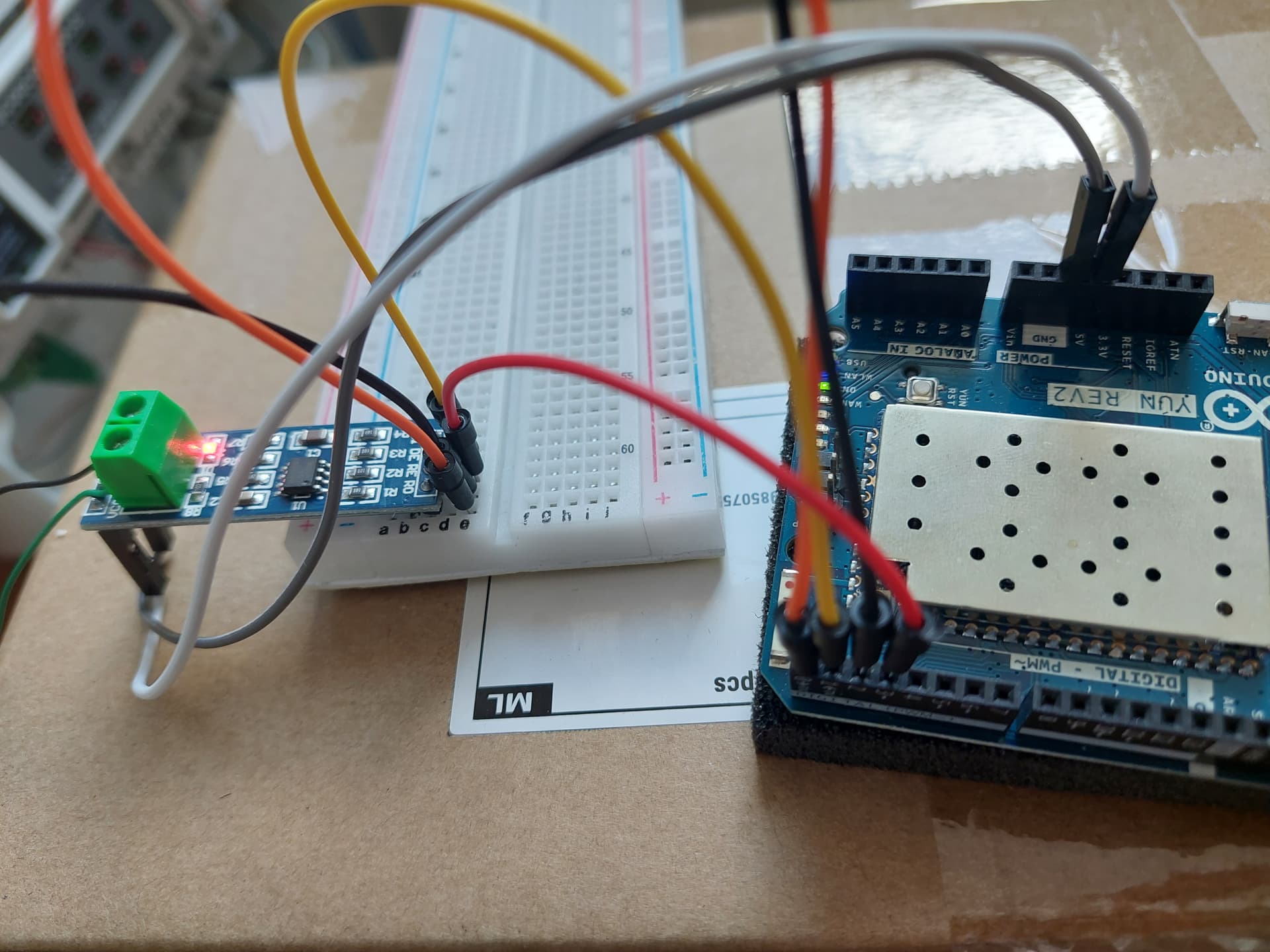
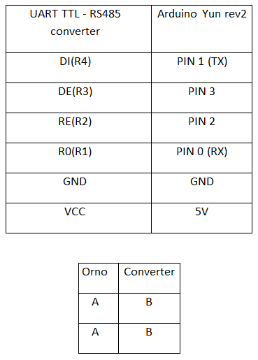
I am trying to read the values sent by the counter "orno or-we-517" via rs485. I am using a UART TTL - RS485 converter. The circuit is shown in the attached photos. I know that the energy meter works correctly, because I can read the values from it after connecting it directly to the computer using an adapter. So I blame the failure on the wrong code or a faulty converter. I tried using different register values in the code, but every time, the effect is the same. I have no idea what is wrong.
In the attachment I also send a list of available registers of the counter.
First, in your code you use the same Serial both for issuing messages to the PC Arduino monitor and for communicating with RS485. This means that all your messages like "test 1" you also send to the modbus line. That won't work.
As far as I can see you are using arduino Yun. This board has an atmega32u4 controller with two Serial ports. First port, which called just "Serial" is used to communicate with a computer via USB, and Serial1 is used to communicate with external modules on pins 0 and 1. You have your RS485 connected to pins 0 and 1, which means you should use Serial1 for it.
To that channel but not the line because Serial is just the virtual USB serial interface, Serial1 is the hardware serial interface the Modbus is connected to (as you mention too a few lines later).
Sorry for being picky but OP might need that clarity.
Sorry I cannot take the time to figure out your frizzy picture, a schematic would be much better as it will be showing all connections, power source, etc.
Thank you for your quick responses!
Unfortunately I am away from home now, but on Tuesday I will be able to try your solutions, and I will try to upload a readable circuit. Thanks again!
Hello again!
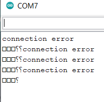
I applied the solution suggested by @b707, which eliminated the problem with strange characters appearing in the serial port monitor. Unfortunately, the connection to the counter still does not work. I keep getting the response "connection error".
@gilshultz
connections:
Arduino is connected to PC via usb cable
I keep experimenting with this value, I have already tried to read one, or four registers, starting from 0000 or from other values, unfortunately without success
Sorry that picture is not a schematic. It needs to show all connections, including power and ground. Links to technical information on the hardware also helps. Do you have a scope or logic analyzer?
Nice link, it even had a schematic Try to do a hand drawn one, start with two boxes run the wires label them and the pins. No need to add pins you do not use. Add the power supply and you should have it. Note if you have enabled the termination on the 485 board. There are available on the internet from such places as Aliexpress 24mhz, try this link: Usb Logic Analyzer 24mhz 8 Channel 24m/seconds Logic Analyzer Debugger For Arm Fpga Logic Analyzer Logic 24m 8ch - Integrated Circuits - AliExpress There is software available on line that works good with it. The front end is a custom chip and is a little sensitive to over voltage. I used a HCT buffer, works great and I do not blow the logic analyzer. The price is inexpensive and it will help a lot.
Print out the value of resultMain and post the value!
Reading 81 values won't succeed as the receive buffer has only 64 entries in that library.
Keep in mind that using the Serial1 interface on the Yun makes that board a Leonardo because you cannot use the Linux part and it's features anymore (the two processors communicate by the serial interface).
I don't know if you are still working on it.
One of the issues I found, was that the ORNO expects an 8E1 communication, ie EVEN parity.
My ORNO is a single phase meter (OR-WE-514) but I assume that the parameters will be the same for both models.