Jim
I just tested the sender box and all buttons from another room in the house and it connected and worked fine. So my only question at this point is do you have any comments about the code.
Then I would like to move on the receiver code and motor and lights driver setup.
regards
Jim
The receiver in the clock ran the Nema 17 stepper motor originally by a Microstep Driver TB6600 RR-2B-RAP controller. Thgetting fe whole clock is powered by a 12 volt battery later to become a 12v 6 amp witch mode power supply.
It was only after I set up the Arduino Nano RF digital and analogue outputs to switch 12 off 24 LED white strips I found I had problems.
- Could not get full brightness with digital outputs while analog outputs worked fine but I only had 6 available A0 - A5.
- Although I could drive with signal transistors even then the digital outputs did not give full brightness
- So that is when I went for opto coupled arduino relay boards to switch the 12 light strips but only the analog outputs would drive them direct and the power required was ok for all 6 to be on together
- So I needed 6 more analog outputs and decided to use another arduino nano without RF hardware to do this by sending it a binary number from 3 digital pins on the clock chip directly connected to three pins of the second chip (8 codes)
- I was getting very curious results like not all relays were on when commanded and even changing the chips and swapping pins certain outputs were not going HIGH?
- Checking on two different relay boards made no difference so there was no fault on the boards or the processor chips?
The next problem was after connecting the stepper motor and controller as previous before the lights experiment to check overall operation I found the motor not responding except by just dithering back and forth on step commands. So I tried all different delays on the stepping command to give the electronics time to settle and reduced the cycle time t no avail. So I just went and bought another controller and set it up using the library [#include stepper.h] only to find exactly the same result! So I am now about to order a new motor unless someone can tell me otherwise like perhaps the RF is inducing crap in the controller signal wires and its not the motor. But of course that should have occurred before the light experiment.
So here is the code on the clock (receiver) chip using commands for the second controller with those for the first commented out.
#include <SPI.h>
#include <nRF24L01.h>
#include <RF24.h>
#include <Stepper.h>

#define CE_PIN   9
#define CS_PIN 10

const uint64_t address = 0xE8E8F0F0E1; // Change this address to match the receiver's address
RF24 radio(CS_PIN, CE_PIN);

// Set up motor control pins
// const int stepPin = 5;
// const int dirPin = 2;
// const int enPin  = 8;
const int stepsPerRevolution = 200;
Stepper myStepper(stepsPerRevolution, 2,3,3,5);

const int enPin1 = 6;
const int enPin2 = 7;

int Button = 0;
uint8_t data = 0;
int fwd = 1;
int rev = -1;

// Stepper motor configuration
// cons int stepsPerRevolution = 400;
// Stepper myStepper(stepsPerRevolution, GND, 3, GND, 5);

void setup() {
  pinMode(A0,OUTPUT);
  pinMode(A1,OUTPUT);
  pinMode(A3,OUTPUT);
  pinMode(A3,OUTPUT);
  pinMode(A6,OUTPUT);
  pinMode(A7,OUTPUT);

//  pinMode(stepPin,OUTPUT);
//  pinMode(dirPin,OUTPUT);
  pinMode(enPin1,OUTPUT);
  pinMode(enPin2,OUTPUT);

  digitalWrite(enPin1,HIGH);
  digitalWrite(enPin2,HIGH);

  Serial.begin(9600);
  radio.begin();
  radio.openReadingPipe(1, address);
  radio.startListening();
}

void loop() {
  if (radio.available()) {
    uint8_t data = 0;
    radio.read(&data, sizeof(data));
    Serial.println("Received: " + String(data) + "  " + String(sizeof(data)));
    delay(1);
    Button = int(data);
  } else {
    Serial.println("No Data");
    Serial.println(millis());
    // delay(1000);
  }

  switch (Button) {
    case 1: // fast fwd
//      digitalWrite(dirPin,HIGH);
//      digitalWrite(stepPin,HIGH);
//      delayMicroseconds(200);
//      digitalWrite(stepPin,LOW);
      myStepper.step(fwd);
      delay(2);
      break;
    case 2: // slow fwd
//      digitalWrite(dirPin,HIGH);
//      digitalWrite(stepPin,HIGH);
//      delay(50);
//      digitalWrite(stepPin,LOW);
      myStepper.step(fwd);
      delay(50);
      break;
    case 3: // slow reverse
//      digitalWrite(dirPin,LOW);
//      digitalWrite(stepPin,HIGH);
//      delay(50);
//      digitalWrite(stepPin,LOW);
      myStepper.step(rev);
      delay(50);
      break;
    case 4: // fast reverse
//      digitalWrite(dirPin,LOW);
//      digitalWrite(stepPin,HIGH);
//      delayMicroseconds(200);
//      digitalWrite(stepPin,LOW);
//      delayMicroseconds(200);
      myStepper.step(rev);
      delay(2);
      break;

    case 7:  // clock running code loop and lights on:
//      digitalWrite(dirPin,HIGH);
//      delay(1); // allow time for slave read

//      digitalWrite(stepPin,HIGH);
      myStepper.step(fwd);
      delay(100);
//      digitalWrite(stepPin,LOW);

      // send binary 111 code all 6 lights on
//      digitalWrite(3,HIGH);
//      delayMicroseconds(50);
//      digitalWrite(4,HIGH);
//      delayMicroseconds(50);
//      digitalWrite(6,HIGH);
//      delayMicroseconds(50);
//     digitalWrite(12,HIGH); // turn on ALL LIGHTS
//      delayMicroseconds(50);
//      digitalWrite(7,HIGH); // ok to read
      // delayMicroseconds(50); // allow read time
      // now these lights all on
      digitalWrite(A0,HIGH);
      delayMicroseconds(50);
      digitalWrite(A1,HIGH);
      delayMicroseconds(50);
      digitalWrite(A2,HIGH);
      delayMicroseconds(50);
      digitalWrite(A3,HIGH);
      delayMicroseconds(50);
      digitalWrite(A4,HIGH);
      delayMicroseconds(50);
      digitalWrite(A5,HIGH);
      delayMicroseconds(50);
      digitalWrite(7,LOW); // finish data read

      Serial.println("Clock ticking");

    case 5: // LIGHT SHOW
// All OFF 1
      // send binary 011 code all 6 lights 1st OFF
      digitalWrite(3,LOW);
      digitalWrite(4,HIGH);
      digitalWrite(6,HIGH);
      digitalWrite(12,LOW); // turn off ALL LIGHTS
      digitalWrite(7,HIGH); // ok to read

      // now these lights all off
      digitalWrite(A0,LOW);
      digitalWrite(A1,LOW);
      digitalWrite(A2,LOW);
      digitalWrite(A3,LOW);
      digitalWrite(A4,LOW);
      digitalWrite(A5,LOW);
      digitalWrite(7,LOW); // finish data read

// All ON 1
      // send binary 111 code all slave lights 1st ON
      digitalWrite(3,HIGH);
      digitalWrite(4,HIGH);
      digitalWrite(6,HIGH);
      digitalWrite(12,HIGH); // turn on ALL LIGHTS
      digitalWrite(7,HIGH); // ok to read

      // now these lights all ON
      digitalWrite(A0,HIGH);
      digitalWrite(A1,HIGH);
      digitalWrite(A2,HIGH);
      digitalWrite(A3,HIGH);
      digitalWrite(A4,HIGH);
      digitalWrite(A5,HIGH);
      digitalWrite(7,LOW); // finish data read

// All OFF 2
      // send binary 011 code all 6 lights 2nd OFF
      digitalWrite(3,LOW);
      digitalWrite(4,HIGH);
      digitalWrite(6,HIGH);
      digitalWrite(12,LOW); // turn off ALL LIGHTS
      digitalWrite(7,HIGH); // ok to read

      // now these lights all off
      digitalWrite(A0,LOW);
      digitalWrite(A1,LOW);
      digitalWrite(A2,LOW);
      digitalWrite(A3,LOW);
      digitalWrite(A4,LOW);
      digitalWrite(A5,LOW);
      digitalWrite(7,LOW); // finish data read

// All ON 2
      // send binary 111 code all slave lights 2nd ON
      digitalWrite(3,HIGH);
      digitalWrite(4,HIGH);
      digitalWrite(6,HIGH);
      digitalWrite(12,HIGH); // turn on ALL LIGHTS
      digitalWrite(7,HIGH); // ok to read

      // now these lights all ON
      digitalWrite(A0,HIGH);
      digitalWrite(A1,HIGH);
      digitalWrite(A2,HIGH);
      digitalWrite(A3,HIGH);
      digitalWrite(A4,HIGH);
      digitalWrite(A5,HIGH);
      digitalWrite(7,LOW); // finish data read

// All OFF 3
      // send binary 011 code all 6 lights 3rd OFF
      digitalWrite(3,LOW);
      digitalWrite(4,HIGH);
      digitalWrite(6,HIGH);
      digitalWrite(12,LOW); // turn off ALL LIGHTS
      digitalWrite(7,HIGH); // ok to read

      // now these lights all off
      digitalWrite(A0,LOW);
      digitalWrite(A1,LOW);
      digitalWrite(A2,LOW);
      digitalWrite(A3,LOW);
      digitalWrite(A4,LOW);
      digitalWrite(A5,LOW);
      digitalWrite(7,LOW); // finish data read

// clockwise ON Swirl
      digitalWrite(A0,HIGH);
      delay(2);
      digitalWrite(A1,HIGH);
      delay(2);
      digitalWrite(A2,HIGH);
      delay(2);
      digitalWrite(A3,HIGH);
      delay(2);
      digitalWrite(A4,HIGH);
      delay(2);
      digitalWrite(A5,HIGH);
      delayMicroseconds(1900); // allow time for slave read
      // Slave follow
      digitalWrite(3,LOW);
      digitalWrite(4,LOW);
      digitalWrite(6,LOW);
      digitalWrite(12,HIGH); // turn on SA0 (slave A0)
      digitalWrite(7,HIGH); // ok to read
      delayMicroseconds(1900); // allow time for slave read
      digitalWrite(7,LOW); // finish read

      digitalWrite(3,HIGH);
      digitalWrite(4,LOW);
      digitalWrite(6,LOW);
      digitalWrite(12,HIGH); // turn on SA1
      digitalWrite(7,HIGH); // ok to read
      delayMicroseconds(1900); // allow time for slave read
      digitalWrite(7,LOW); // finish read

      digitalWrite(3,LOW);
      digitalWrite(4,HIGH);
      digitalWrite(6,LOW);
      digitalWrite(12,HIGH); // turn on SA2
      digitalWrite(7,HIGH); // ok to read
      delayMicroseconds(1900); // allow time for slave read
      digitalWrite(7,LOW); // finish read

      digitalWrite(3,HIGH);
      digitalWrite(4,HIGH);
      digitalWrite(6,LOW);
      digitalWrite(12,HIGH); // turn on SA3
      digitalWrite(7,HIGH); // ok to read
      delayMicroseconds(1900); // allow time for slave read
      digitalWrite(7,LOW); // finish read

      digitalWrite(3,LOW);
      digitalWrite(4,LOW);
      digitalWrite(6,HIGH);
      digitalWrite(12,HIGH); // turn on SA4
      digitalWrite(7,HIGH); // ok to read
      delayMicroseconds(1900); // allow time for slave read
      digitalWrite(7,LOW); // finish read

      digitalWrite(3,HIGH);
      digitalWrite(4,LOW);
      digitalWrite(6,HIGH);
      digitalWrite(12,HIGH); // turn on SA5
      digitalWrite(7,HIGH); // ok to read
      delayMicroseconds(1900); // allow time for slave read
      digitalWrite(7,LOW); // finish read

// Anticlockwise OFF swirl
      // Slave starts
      digitalWrite(3,HIGH);
      digitalWrite(4,LOW);
      digitalWrite(6,HIGH);
      digitalWrite(12,LOW); // turn off SA5
      digitalWrite(7,HIGH); // ok to read
      delayMicroseconds(1900); // allow time for slave read
      digitalWrite(7,LOW); // finish read

      digitalWrite(3,LOW);
      digitalWrite(4,LOW);
      digitalWrite(6,HIGH);
      digitalWrite(12,LOW); // turn off SA4
      digitalWrite(7,HIGH); // ok to read
      delayMicroseconds(1900); // allow time for slave read
      digitalWrite(7,LOW); // finish read

      digitalWrite(3,HIGH);
      digitalWrite(4,HIGH);
      digitalWrite(6,LOW);
      digitalWrite(12,LOW); // turn off SA3
      digitalWrite(7,HIGH); // ok to read
      delayMicroseconds(1900); // allow time for slave read
      digitalWrite(7,LOW); // finish read

      digitalWrite(3,LOW);
      digitalWrite(4,HIGH);
      digitalWrite(6,LOW);
      digitalWrite(12,LOW); // turn off SA2
      digitalWrite(7,HIGH); // ok to read
      delayMicroseconds(1900); // allow time for slave read
      digitalWrite(7,LOW); // finish read

      digitalWrite(3,HIGH);
      digitalWrite(4,LOW);
      digitalWrite(6,LOW);
      digitalWrite(12,LOW); // turn off SA1
      digitalWrite(7,HIGH); // ok to read
      delayMicroseconds(1900); // allow time for slave read
      digitalWrite(7,LOW); // finish read

      digitalWrite(3,LOW);
      digitalWrite(4,LOW);
      digitalWrite(6,LOW);
      digitalWrite(12,LOW); // turn off SA0
      digitalWrite(7,HIGH); // ok to read
      delayMicroseconds(1900); // allow time for slave read
      digitalWrite(7,LOW); // finish read
      // Finish OFF swirl

// Vertical Down ON
      digitalWrite(A0,HIGH);
      // slave SA5 ON
      digitalWrite(3,HIGH);
      digitalWrite(4,LOW);
      digitalWrite(6,HIGH);
      digitalWrite(12,HIGH); // turn on SA5
      digitalWrite(7,HIGH); // ok to read
      delayMicroseconds(1900); // allow time for slave read
      digitalWrite(7,LOW); // finish read

      delay(2);
      digitalWrite(A1,HIGH);
      // slave SA4 ON
      digitalWrite(3,LOW);
      digitalWrite(4,LOW);
      digitalWrite(6,HIGH);
      digitalWrite(12,HIGH); // turn on SA4
      digitalWrite(7,HIGH); // ok to read
      delayMicroseconds(1900); // allow time for slave read
      digitalWrite(7,LOW); // finish read

      delay(2);
      digitalWrite(A2,HIGH);
      // slave SA3 ON
      digitalWrite(3,HIGH);
      digitalWrite(4,HIGH);
      digitalWrite(6,LOW);
      digitalWrite(12,HIGH); // turn on SA3
      digitalWrite(7,HIGH); // ok to read
      delayMicroseconds(1900); // allow time for slave read
      digitalWrite(7,LOW); // finish read

      delay(2);
      digitalWrite(A3,HIGH);
      // slave SA2 ON
      digitalWrite(3,LOW);
      digitalWrite(4,HIGH);
      digitalWrite(6,LOW);
      digitalWrite(12,HIGH); // turn on SA2
      digitalWrite(7,HIGH); // ok to read
      delayMicroseconds(1900); // allow time for slave read
      digitalWrite(7,LOW); // finish read

      delay(2);
      digitalWrite(A4,HIGH);
      // slave SA1 ON
      digitalWrite(3,HIGH);
      digitalWrite(4,LOW);
      digitalWrite(6,LOW);
      digitalWrite(12,HIGH); // turn on SA1
      digitalWrite(7,HIGH); // ok to read
      delayMicroseconds(1900); // allow time for slave read
      digitalWrite(7,LOW); // finish read

      delay(2);
      digitalWrite(A5,HIGH);
      // slave SA0 ON
      digitalWrite(3,LOW);
      digitalWrite(4,LOW);
      digitalWrite(6,LOW);
      digitalWrite(12,HIGH); // turn on SA0
      digitalWrite(7,HIGH); // ok to read
      delayMicroseconds(1900); // allow time for slave read
      digitalWrite(7,LOW); // finish read

      break;
 }
  Button = 0;
}
Thank you so much for any advice you may give.
Can you show a wiring diagram, the description and code are somewhat confusing.
Is your stepper driver connected to pins 2, 3, and 5? You appear to be using pin 3 for one of your relay signal pins to the 2nd arduino board.
You have not set any of the digital pins to output mode, as well as a couple of the analog pins (A4 and A5).
This is totally wrong, A6 and A7 are analog input only on a Nano:
< edit >
Can you post the original code with which the stepper motor worked? The Stepper library does not seem to be compatible with the TB6600 stepper motor driver.
Thanks David..
The wiring is changing as I test various combinations on the bench using a breadboard so I am trying to show only real problems one at a time. If you look at the thread my reply to jim includes all the code except I have now rearranged the case statements from 1 through 7 in order just in case my putting 7 before 5 and leaving out 6 was a cause of any logical bug.
- Regarding the motor controller the code shown was not used on the TB6600 that code has been commented out and the new code is for the Keystudio L298N controller I am testing now.
- Because time it short and I have physical work to do I have ordered a new motor with premium delivery which is less powerful but adequate especially since I am about to fit lead weight balance to the clock hands.
- I should be able to get a refund or replacement for the original if it proves faulty
- All the controller connections are exactly as indicated in the code
But for now I have no motor. However I do have a real problem with the Arduino Nano the clock chip which is controlling both the motor and lights.
- With minimal hardware connected to the clock chip: Digital outputs on A0, A1, A2, A3 and those pins connected to a 4 by opto coupled arduino 12 V relay board (powered from a battery), running the receiver code with Button = 7 received from the remote station, only relays A0, A3 and A4 fire? No high is even present on the A2 pin of the arduino but the code definitely requires it!
- I changed the chip for an identical one and I get the same result
I have no idea about this one.
Pin 12 is still used, which is part of the SPI bus.
Pin A3 is set as output twice. Pin A6 and A7 are set as output, which is not possible.
If the Nano board is powered with 12V, then the voltage regulator might get too hot. Some relay modules need almost no current, other modules need 5...20mA per input.
Because of the relays and the stepper motor, the grounding must be good. The grounds must be connected and the current from the motors should not disturb the Arduino board.
It is possible to fix the project.
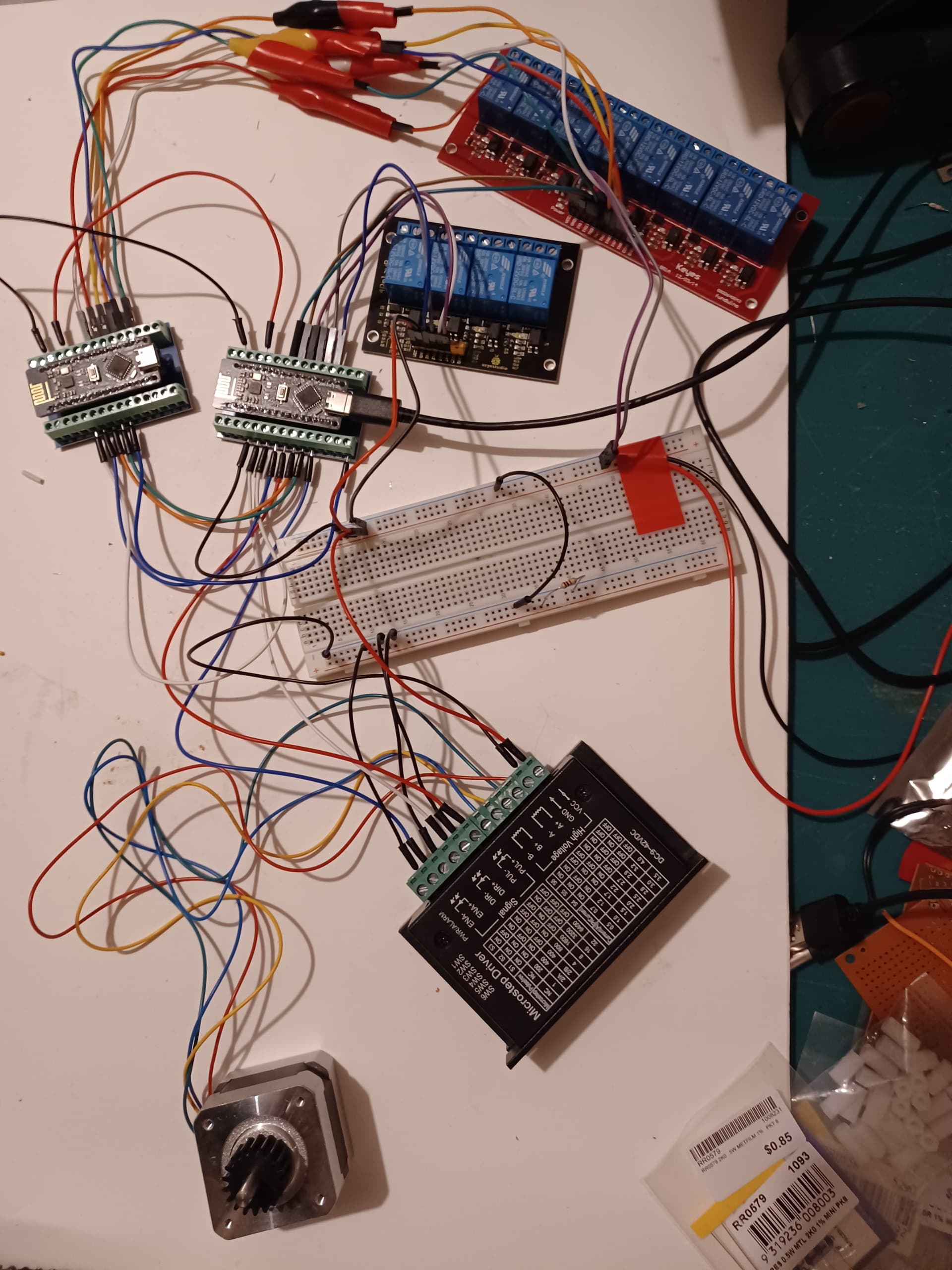
I suggest to fix everything step by step. Start with the hardware. Do you have a schematic ? Can you draw on a piece of paper how it is wired. Can you give links to the relay module and all the other parts ? Can you show a photo of the project ?
When you buy parts from AliExpress/Ebay/Amazon, then you might have bought counterfeit modules (such as the nRF24L01+ chip) or components with very bad quality (the relays) or modules with the wrong circuit. Those who sell those things really don't care if it is reliable.
There are also good sellers that use genuine components, such as Adafruit, Sparkfun, Pololu.
Thank you Koepel
Yes I am sure l can get all you have requested asap.. but I don't have access to quick pictorial circuit images so I'll just draw the thing.. With the new motor the controller I would prefer to use is the TB6600 so I'll return the clock code to that configuration.. I am guessing the failure to get a HIGH on A2 which is consistent on two of my nano RF chips is a fault of the chip not expected on the real thing? It seems a pity because in other respects the nano's were behaving quite well. Thanks for the tip on 12V supply potential problem for Arduino's. On that subject it would be relatively easy to build a 5V supply to be on the safe side.
I don't think local Jaycar Elec has arduino nano with built in radio so should I just go buy new arduino nano chips and separate RF modules or wait for more information and testing etc.
regards
Koepel yes fixing the missing A2 OUTPUT fixed the missing A2 HIGH.. and yes A6, A7 are not required. So I will now wire up the whole setup with slave Arduino and two relay boards with 12 outputs, give it a test and draw a circuit diagram and provide you all the information you need.
Just one point if I run the Arduino's from 12V on the bench for an hour or so and they don't get hot or fail is that a pass saving me from buying more expensive hardware (I am already over budget). Thanks so much..
regards
Before you get into new problems, please give us more information.
These pages have a schematic and code for the "RF-Nano":
- https://github.com/emakefun/rf-nano
- https://emakefun-docs.readthedocs.io/zh-cn/latest/open_source_hardware/rf-nano_v3_0/
It seems straightforward. I assume that your board is working.
Setting the pinMode for A6 and A7 seems to be a bug in the Arduino software.
Pinmode: https://github.com/arduino/ArduinoCore-avr/blob/master/cores/arduino/wiring_digital.c#L29
digitalPinToPort: https://github.com/arduino/ArduinoCore-avr/blob/master/cores/arduino/Arduino.h#L178
digital_pin_to_port_PGM: https://github.com/arduino/ArduinoCore-avr/blob/master/variants/standard/pins_arduino.h#L150
There is nothing declared in the table for A6 and A7. There is also no check and no error return. The check "if (port == NOT_A_PIN) return;" does not work and conversion to the Port mode register will also be unpredictable. Anything can happen if you set the pinMode for A6 or A7.
Ok thanks
Thank you Koepel please bear with me I am tired and have been busy with physical work on the clock. I also take your advice and I will build a 5V 1Amp supply from the 12V input to run the Arduinos.
I have a new motor and have been working on setting it up with all connections as it is on the bench and draw a circuit diagram. I use the original TB6600 controller so have reverted the code back to suit that controller and it works ok.
I found D12 was able to be set HIGH or LOW so for communication with the slave Arduino I have (D3, D4, D6 data), (D7 data available), (D12 lights ON or OFF). The slave drives the other 6 inputs to a relay board via A0 - A5 which does work because all lights come on as required.
The problem I am seeing now is with the sending Arduino which sends button presses to the Receiving Arduino in the clock. It is sending a signal (int value 7 which is the clock tic) without any button press to send that code or any code? Other buttons (fast fwd/rev, slow fwd/rev and light show) appear to be working fine except the timing needs correcting. I'll include a circuit diagram of the sending box.
Here is the clock it's 1.5 M in diameter.. time is not right because the gearbox has not been assembled.. which is awaiting the electrical components.

And here is my bench setup..
Here is the sender box..
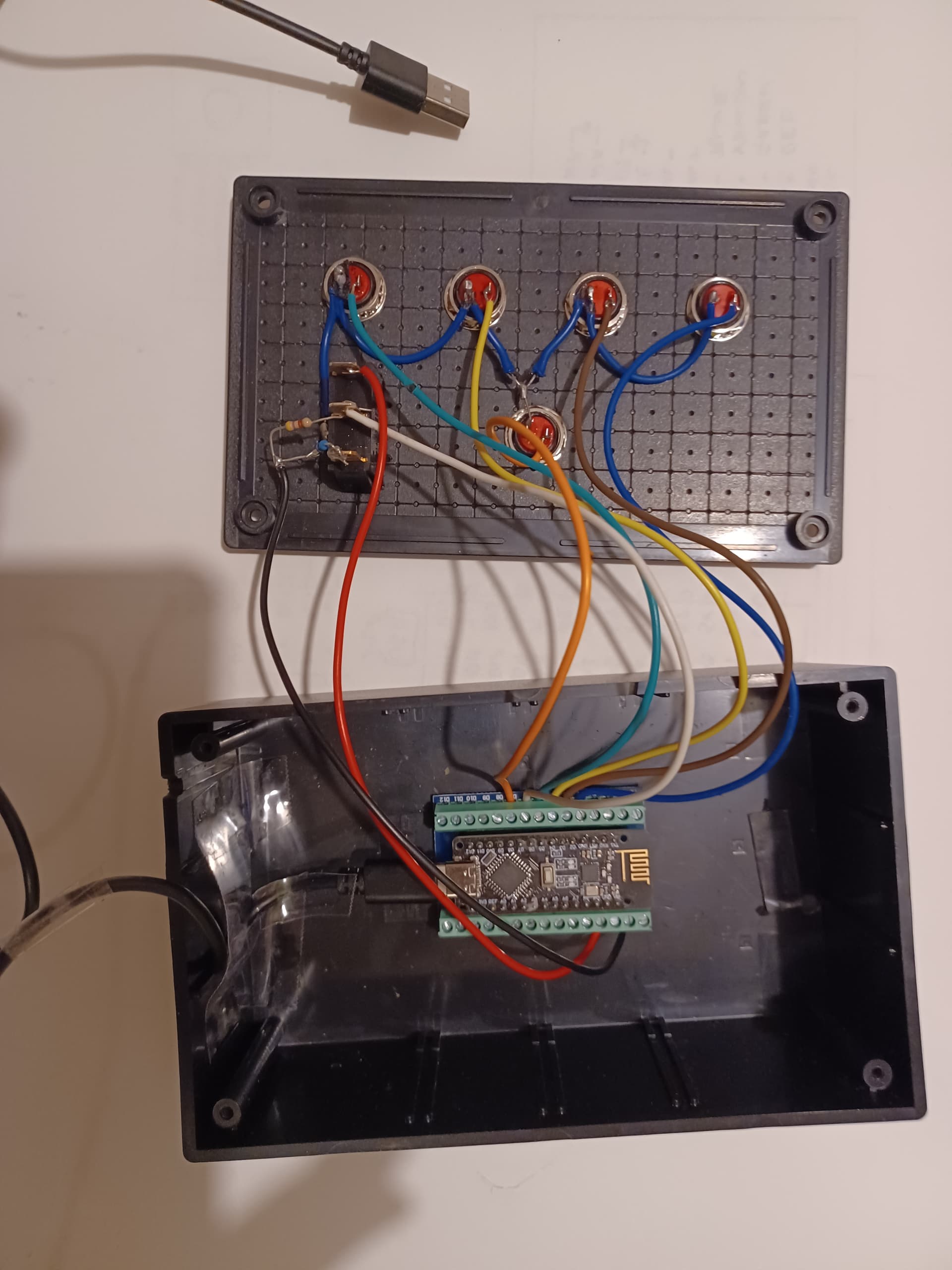
Here is the code for the sender box which I know is the source of the problem because when the USB is unplugged the spurious "7" signal stops s it is not in the receiver on the clock.
// constants won't change. They're used here to set pin numbers:
#include <SPI.h>
#include <RF24.h>
#include <nRF24L01.h>

#define CE_PIN       9   // D9 = Chip Enable (CE) for nRF24L01+
#define CS_PIN       10  // D10 = Chip Select (CS) for nRF24L01+
RF24 radio(CS_PIN, CE_PIN);

// #define CHANNEL_WRITE   123456789 // same PIPE as for RX
const uint64_t address = 0xE8E8F0F0E1; // Change this address to match the receiver's address

const int ffwd    = 1;
const int slwfwd  = 2;
const int slwrev  = 3;
const int frev    = 4;
const int lights  = 5;
const int clock    = 7;
const int off     = 8;

const int BTN1 = 2;  // ffwd pushbutton pin
const int BTN2 = 3;  // slfwd
const int BTN3 = 4;  // slrev
const int BTN4 = 5;  // frev
const int BTN5 = 6;  // clock
const int BTN6 = 7;  // lights
const int LedPin = 13;  // the number of the LED pin
unsigned long Tick = 0;

// variables will change:
void setup() {

  // initialize the LED pin as an output:
  pinMode(LedPin, OUTPUT);
  digitalWrite(LedPin, LOW);
  // initialize the pushbutton pins as inputs:
  pinMode(BTN1, INPUT_PULLUP);
  pinMode(BTN2, INPUT_PULLUP);
  pinMode(BTN3, INPUT_PULLUP);
  pinMode(BTN4, INPUT_PULLUP);
  pinMode(BTN5, INPUT);  // clock switch
  pinMode(BTN6, INPUT_PULLUP);

// Configure the Radio
  Serial.begin(9600);
  radio.begin();
  radio.openWritingPipe(address); // For Outgoing Data
  radio.setDataRate(RF24_1MBPS); // Small Bandwidth
  radio.setPALevel(RF24_PA_MAX);
  radio.stopListening();

  // radio.setPayloadSize(8); // Size of the Data we will Transmit
  // radio.setAutoAck(true); // Allows us to check if the Transmission Succeeded
  // We technically don't need to open a Reading Pipe for a Transmit-Only Device!
  // radio.openReadingPipe(1, CHANNEL_READ); // For Incoming Data
  // We need to open the Writing Pipe in order to Transmit data
}

void loop() {
  // fast forward
  while (digitalRead(BTN1) == LOW)
    {
    radio.write(&ffwd, sizeof(ffwd));
    Serial.println("Sending ffwd");
    delayMicroseconds(100);
    }
  // slow fwd Button = 2
  while (digitalRead(BTN2) == LOW)
    {
      radio.write(&slwfwd, sizeof(slwfwd));
      delayMicroseconds(100);
      Serial.println("Sending slwfwd");
    }
  // slow rev
  while (digitalRead(BTN3) == LOW)
    {
      radio.write(&slwrev, sizeof(slwrev));
      delayMicroseconds(100);
      Serial.println("Sending slwrev");
    }
  // fast reverse
  while (digitalRead(BTN4) == LOW)
    {
      radio.write(&frev, sizeof(frev));
      delayMicroseconds(100);
      Serial.println("Sending frev");
    }
  while (digitalRead(BTN6) == LOW)
    {
      radio.write(&lights, sizeof(lights)); //Light show
      delayMicroseconds(100);
      Serial.println("Sending lights");
    }
  if (digitalRead(BTN5) == HIGH && millis() - Tick > 1500) {  // clock switch is on
      // Serial.println(millis() - Tick);
      radio.write(&clock, sizeof(clock)); //Send clock code 7
      Tick = millis();
      Serial.println("Sending clock");
    }
  if (digitalRead(BTN5) == LOW) {  // Set clock OFF Flag
      radio.write(&clock, sizeof(off)); //Send code 8
      Serial.println("Clock OFF");
    }
}
And here is the code for the receiver as it now stands with the working motor.
#include <SPI.h>
#include <nRF24L01.h>
#include <RF24.h>
// #include <Stepper.h>

#define CE_PIN 9
#define CS_PIN 10

const uint64_t address = 0xE8E8F0F0E1;  // Change this address to match the receiver's address
RF24 radio(CS_PIN, CE_PIN);

// Set up motor control pins
const int stepPin = 5;
const int dirPin = 2;
const int enPin  = 8;

const int enPin1 = 6;
const int enPin2 = 7;

int Button = 0;
uint8_t data = 0;
int fwd = 1;
int rev = -1;

// Stepper motor configuration
const int stepsPerRevolution = 400;
// Stepper myStepper(stepsPerRevolution, GND, 3, GND, 5);

void setup() {
  pinMode(A0, OUTPUT);
  pinMode(A1, OUTPUT);
  pinMode(A2, OUTPUT);
  pinMode(A3, OUTPUT);
  pinMode(A4, OUTPUT);
  pinMode(A5, OUTPUT);

  pinMode(stepPin,OUTPUT);
  pinMode(dirPin,OUTPUT);

  digitalWrite(enPin, LOW);  // Motor in auto control HIGH = off

  Serial.begin(9600);
  radio.begin();
  radio.openReadingPipe(1, address);
  radio.startListening();
}

void loop() {
  if (radio.available()) {
    uint8_t data = 0;
    radio.read(&data, sizeof(data));
    Serial.println("Received: " + String(data) + "  " + String(sizeof(data)));
    delay(1);
    Button = int(data);
  } else {
    Serial.println("No Data");
    Serial.println(millis());
    delay(500);
  }
  if (Button > 0 && Button < 8) {  // ON state
    switch (Button) {
      case 1:  // fast fwd
        digitalWrite(dirPin,HIGH);
        digitalWrite(stepPin,HIGH);
        delayMicroseconds(200);
        digitalWrite(stepPin,LOW);
        delay(2);
        break;
      case 2:  // slow fwd
        digitalWrite(dirPin,HIGH);
        digitalWrite(stepPin,HIGH);
        delay(50);
        digitalWrite(stepPin,LOW);
        delay(50);
        break;
      case 3:  // slow reverse
        digitalWrite(dirPin,LOW);
        digitalWrite(stepPin,HIGH);
        delay(50);
        digitalWrite(stepPin,LOW);
        delay(50);
        break;
      case 4:  // fast reverse
        digitalWrite(dirPin,LOW);
        digitalWrite(stepPin,HIGH);
        delayMicroseconds(200);
        digitalWrite(stepPin,LOW);
        delayMicroseconds(200);
        delay(2);
        break;

      case 5:  // LIGHT SHOW
               // All OFF 1
        // send binary 011 code all 6 lights 1st OFF
        digitalWrite(3, LOW);
        digitalWrite(4, HIGH);
        digitalWrite(6, HIGH);
        digitalWrite(12, LOW);  // turn off ALL LIGHTS
        digitalWrite(7, HIGH);  // ok to read

        // now these lights all off
        digitalWrite(A0, LOW);
        digitalWrite(A1, LOW);
        digitalWrite(A2, LOW);
        digitalWrite(A3, LOW);
        digitalWrite(A4, LOW);
        digitalWrite(A5, LOW);
        digitalWrite(7, LOW);  // finish data read

        // All ON 1
        // send binary 111 code all slave lights 1st ON
        digitalWrite(3, HIGH);
        digitalWrite(4, HIGH);
        digitalWrite(6, HIGH);
        digitalWrite(12, HIGH);  // turn on ALL LIGHTS
        digitalWrite(7, HIGH);   // ok to read

        // now these lights all ON
        digitalWrite(A0, HIGH);
        digitalWrite(A1, HIGH);
        digitalWrite(A2, HIGH);
        digitalWrite(A3, HIGH);
        digitalWrite(A4, HIGH);
        digitalWrite(A5, HIGH);
        digitalWrite(7, LOW);  // finish data read

        // All OFF 2
        // send binary 011 code all 6 lights 2nd OFF
        digitalWrite(3, LOW);
        digitalWrite(4, HIGH);
        digitalWrite(6, HIGH);
        digitalWrite(12, LOW);  // turn off ALL LIGHTS
        digitalWrite(7, HIGH);  // ok to read

        // now these lights all off
        digitalWrite(A0, LOW);
        digitalWrite(A1, LOW);
        digitalWrite(A2, LOW);
        digitalWrite(A3, LOW);
        digitalWrite(A4, LOW);
        digitalWrite(A5, LOW);
        digitalWrite(7, LOW);  // finish data read

        // All ON 2
        // send binary 111 code all slave lights 2nd ON
        digitalWrite(3, HIGH);
        digitalWrite(4, HIGH);
        digitalWrite(6, HIGH);
        digitalWrite(12, HIGH);  // turn on ALL LIGHTS
        digitalWrite(7, HIGH);   // ok to read

        // now these lights all ON
        digitalWrite(A0, HIGH);
        digitalWrite(A1, HIGH);
        digitalWrite(A2, HIGH);
        digitalWrite(A3, HIGH);
        digitalWrite(A4, HIGH);
        digitalWrite(A5, HIGH);
        digitalWrite(7, LOW);  // finish data read

        // All OFF 3
        // send binary 011 code all 6 lights 3rd OFF
        digitalWrite(3, LOW);
        digitalWrite(4, HIGH);
        digitalWrite(6, HIGH);
        digitalWrite(12, LOW);  // turn off ALL LIGHTS
        digitalWrite(7, HIGH);  // ok to read

        // now these lights all off
        digitalWrite(A0, LOW);
        digitalWrite(A1, LOW);
        digitalWrite(A2, LOW);
        digitalWrite(A3, LOW);
        digitalWrite(A4, LOW);
        digitalWrite(A5, LOW);
        digitalWrite(7, LOW);  // finish data read

        // clockwise ON Swirl
        digitalWrite(A0, HIGH);
        delay(2);
        digitalWrite(A1, HIGH);
        delay(2);
        digitalWrite(A2, HIGH);
        delay(2);
        digitalWrite(A3, HIGH);
        delay(2);
        digitalWrite(A4, HIGH);
        delay(2);
        digitalWrite(A5, HIGH);
        delayMicroseconds(1900);  // allow time for slave read
        // Slave follow
        digitalWrite(3, LOW);
        digitalWrite(4, LOW);
        digitalWrite(6, LOW);
        digitalWrite(12, HIGH);   // turn on SA0
        digitalWrite(7, HIGH);    // ok to read
        delayMicroseconds(1900);  // allow time for slave read
        digitalWrite(7, LOW);     // finish read

        digitalWrite(3, HIGH);
        digitalWrite(4, LOW);
        digitalWrite(6, LOW);
        digitalWrite(12, HIGH);   // turn on SA1
        digitalWrite(7, HIGH);    // ok to read
        delayMicroseconds(1900);  // allow time for slave read
        digitalWrite(7, LOW);     // finish read

        digitalWrite(3, LOW);
        digitalWrite(4, HIGH);
        digitalWrite(6, LOW);
        digitalWrite(12, HIGH);   // turn on SA2
        digitalWrite(7, HIGH);    // ok to read
        delayMicroseconds(1900);  // allow time for slave read
        digitalWrite(7, LOW);     // finish read

        digitalWrite(3, HIGH);
        digitalWrite(4, HIGH);
        digitalWrite(6, LOW);
        digitalWrite(12, HIGH);   // turn on SA3
        digitalWrite(7, HIGH);    // ok to read
        delayMicroseconds(1900);  // allow time for slave read
        digitalWrite(7, LOW);     // finish read

        digitalWrite(3, LOW);
        digitalWrite(4, LOW);
        digitalWrite(6, HIGH);
        digitalWrite(12, HIGH);   // turn on SA4
        digitalWrite(7, HIGH);    // ok to read
        delayMicroseconds(1900);  // allow time for slave read
        digitalWrite(7, LOW);     // finish read

        digitalWrite(3, HIGH);
        digitalWrite(4, LOW);
        digitalWrite(6, HIGH);
        digitalWrite(12, HIGH);   // turn on SA5
        digitalWrite(7, HIGH);    // ok to read
        delayMicroseconds(1900);  // allow time for slave read
        digitalWrite(7, LOW);     // finish read

        // Anticlockwise OFF swirl
        // Slave starts
        digitalWrite(3, HIGH);
        digitalWrite(4, LOW);
        digitalWrite(6, HIGH);
        digitalWrite(12, LOW);    // turn off SA5
        digitalWrite(7, HIGH);    // ok to read
        delayMicroseconds(1900);  // allow time for slave read
        digitalWrite(7, LOW);     // finish read

        digitalWrite(3, LOW);
        digitalWrite(4, LOW);
        digitalWrite(6, HIGH);
        digitalWrite(12, LOW);    // turn off SA4
        digitalWrite(7, HIGH);    // ok to read
        delayMicroseconds(1900);  // allow time for slave read
        digitalWrite(7, LOW);     // finish read

        digitalWrite(3, HIGH);
        digitalWrite(4, HIGH);
        digitalWrite(6, LOW);
        digitalWrite(12, LOW);    // turn off SA3
        digitalWrite(7, HIGH);    // ok to read
        delayMicroseconds(1900);  // allow time for slave read
        digitalWrite(7, LOW);     // finish read

        digitalWrite(3, LOW);
        digitalWrite(4, HIGH);
        digitalWrite(6, LOW);
        digitalWrite(12, LOW);    // turn off SA2
        digitalWrite(7, HIGH);    // ok to read
        delayMicroseconds(1900);  // allow time for slave read
        digitalWrite(7, LOW);     // finish read

        digitalWrite(3, HIGH);
        digitalWrite(4, LOW);
        digitalWrite(6, LOW);
        digitalWrite(12, LOW);    // turn off SA1
        digitalWrite(7, HIGH);    // ok to read
        delayMicroseconds(1900);  // allow time for slave read
        digitalWrite(7, LOW);     // finish read

        digitalWrite(3, LOW);
        digitalWrite(4, LOW);
        digitalWrite(6, LOW);
        digitalWrite(12, LOW);    // turn off SA0
        digitalWrite(7, HIGH);    // ok to read
        delayMicroseconds(1900);  // allow time for slave read
        digitalWrite(7, LOW);     // finish read
        // Finish OFF swirl

        // Vertical Down ON
        digitalWrite(A0, HIGH);
        // slave SA5 ON
        digitalWrite(3, HIGH);
        digitalWrite(4, LOW);
        digitalWrite(6, HIGH);
        digitalWrite(12, HIGH);   // turn on SA5
        digitalWrite(7, HIGH);    // ok to read
        delayMicroseconds(1900);  // allow time for slave read
        digitalWrite(7, LOW);     // finish read

        delay(2);
        digitalWrite(A1, HIGH);
        // slave SA4 ON
        digitalWrite(3, LOW);
        digitalWrite(4, LOW);
        digitalWrite(6, HIGH);
        digitalWrite(12, HIGH);   // turn on SA4
        digitalWrite(7, HIGH);    // ok to read
        delayMicroseconds(1900);  // allow time for slave read
        digitalWrite(7, LOW);     // finish read

        delay(2);
        digitalWrite(A2, HIGH);
        // slave SA3 ON
        digitalWrite(3, HIGH);
        digitalWrite(4, HIGH);
        digitalWrite(6, LOW);
        digitalWrite(12, HIGH);   // turn on SA3
        digitalWrite(7, HIGH);    // ok to read
        delayMicroseconds(1900);  // allow time for slave read
        digitalWrite(7, LOW);     // finish read

        delay(2);
        digitalWrite(A3, HIGH);
        // slave SA2 ON
        digitalWrite(3, LOW);
        digitalWrite(4, HIGH);
        digitalWrite(6, LOW);
        digitalWrite(12, HIGH);   // turn on SA2
        digitalWrite(7, HIGH);    // ok to read
        delayMicroseconds(1900);  // allow time for slave read
        digitalWrite(7, LOW);     // finish read

        delay(2);
        digitalWrite(A4, HIGH);
        // slave SA1 ON
        digitalWrite(3, HIGH);
        digitalWrite(4, LOW);
        digitalWrite(6, LOW);
        digitalWrite(12, HIGH);   // turn on SA1
        digitalWrite(7, HIGH);    // ok to read
        delayMicroseconds(1900);  // allow time for slave read
        digitalWrite(7, LOW);     // finish read

        delay(2);
        digitalWrite(A5, HIGH);
        // slave SA0 ON
        digitalWrite(3, LOW);
        digitalWrite(4, LOW);
        digitalWrite(6, LOW);
        digitalWrite(12, HIGH);   // turn on SA0
        digitalWrite(7, HIGH);    // ok to read
        delayMicroseconds(1900);  // allow time for slave read
        digitalWrite(7, LOW);     // finish read
        break;

      case 6:

      case 7:  // clock running code loopd and lights on:
        digitalWrite(dirPin,HIGH);
        delay(1); // allow time for slave read
        digitalWrite(stepPin,HIGH);
        delay(100);
        digitalWrite(stepPin,LOW);

        // send binary 111 code all 6 lights on
        digitalWrite(3, HIGH);
        digitalWrite(4, HIGH);
        digitalWrite(6, HIGH);
        digitalWrite(12, HIGH);  // turn on ALL LIGHTS
        digitalWrite(7, HIGH);   // ok to read
                                 // delayMicroseconds(50); // allow read time
                                 // now these lights all on
        digitalWrite(A0, HIGH);
        digitalWrite(A1, HIGH);
        digitalWrite(A2, HIGH);
        digitalWrite(A3, HIGH);
        digitalWrite(A4, HIGH);
        digitalWrite(A5, HIGH);
        digitalWrite(7, LOW);  // finish data read

        Serial.println("Clock ticking");
    }
  } else {
    // send binary 011 code all 6 lights OFF
    digitalWrite(3, LOW);
    digitalWrite(4, HIGH);
    digitalWrite(6, HIGH);
    digitalWrite(12, LOW);  // turn off ALL LIGHTS
    digitalWrite(7, HIGH);  // ok to read

    // now these lights all off
    digitalWrite(A0, LOW);
    digitalWrite(A1, LOW);
    digitalWrite(A2, LOW);
    digitalWrite(A3, LOW);
    digitalWrite(A4, LOW);
    digitalWrite(A5, LOW);
    digitalWrite(7, LOW);  // finish data read
    Serial.println("Clock OFF");
  }
}
Best regards to all thank you so much..
2 Likes
What have you got in place to keep pin 6 (BTN5) LOW when the button is not pressed ?
Simple mistake in the code. You are sending the "clock" signal when you meant to send the "off" signal.
  if (digitalRead(BTN5) == HIGH && millis() - Tick > 1500) {  // clock switch is on
      // Serial.println(millis() - Tick);
      radio.write(&clock, sizeof(clock)); //Send clock code 7
      Tick = millis();
      Serial.println("Sending clock");
    }
  if (digitalRead(BTN5) == LOW) {  // Set clock OFF Flag
      radio.write(&clock, sizeof(off)); //Send code 8
      Serial.println("Clock OFF");
    }
1 Like
Sure, you can set it HIGH or LOW, but it is the MISO line of the SPI bus, connected to the nRF24L01. As long as you do not set the pinMode to OUTPUT you will just be turning the internal pullup ON/OFF, and the SPI data is likely fast enough to not be noticeable on the device (relay?) you are driving. DO NOT set the pinMode to OUTPUT, that could potentially destroy the nRF24L01!!!!!
1 Like
Hello
I use pullups on all but pin 5 because that is just a switch.. I think I can see a problem around that but not sure what it is. I'll post the circuit diagrams for sender and clock to Koepel as before..
regards and thanks
 // initialize the pushbutton pins as inputs:
  pinMode(BTN1, INPUT_PULLUP);
  pinMode(BTN2, INPUT_PULLUP);
  pinMode(BTN3, INPUT_PULLUP);
  pinMode(BTN4, INPUT_PULLUP);
  pinMode(BTN5, INPUT);  // clock switch
  pinMode(BTN6, INPUT_PULLUP);
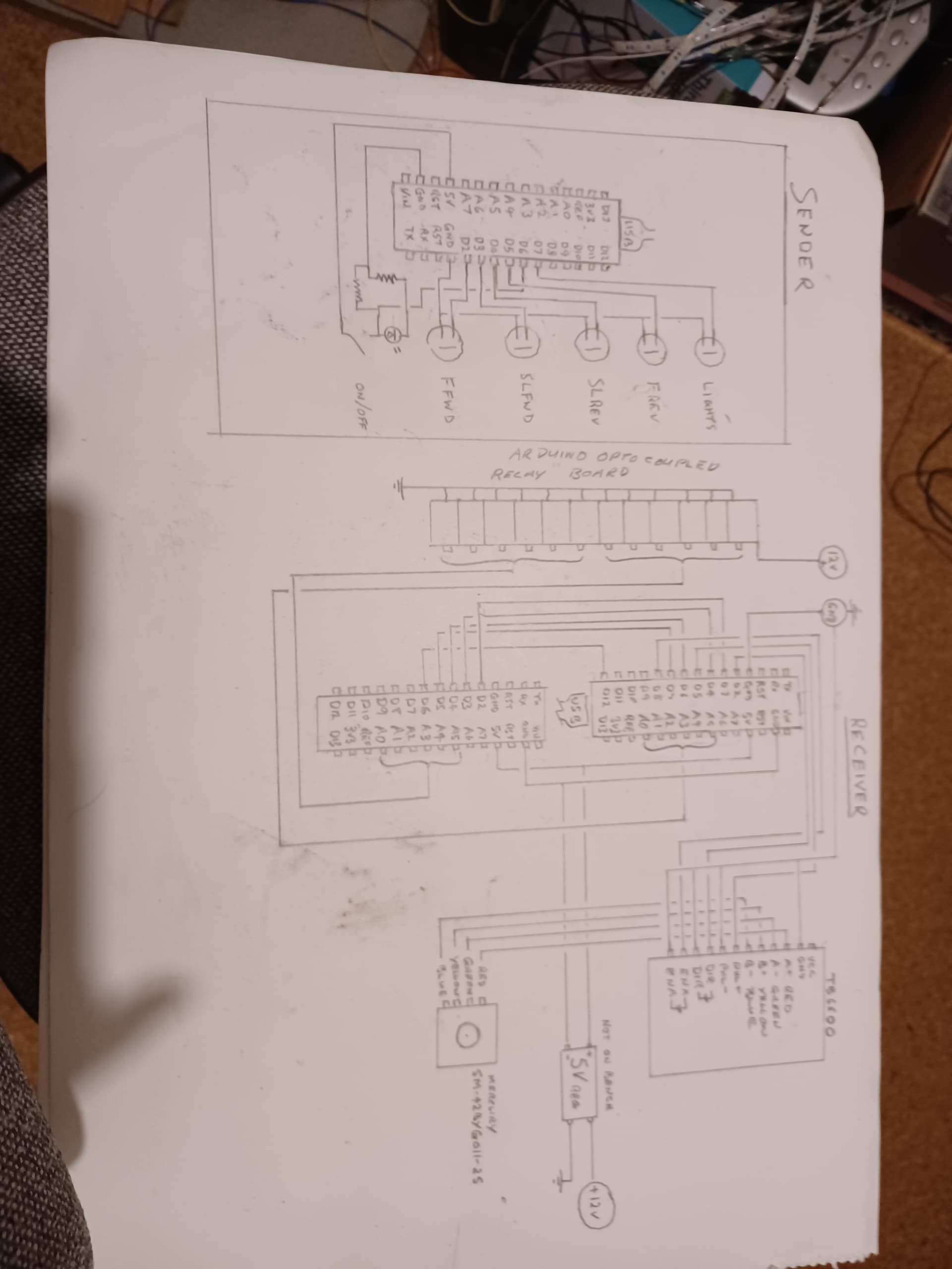
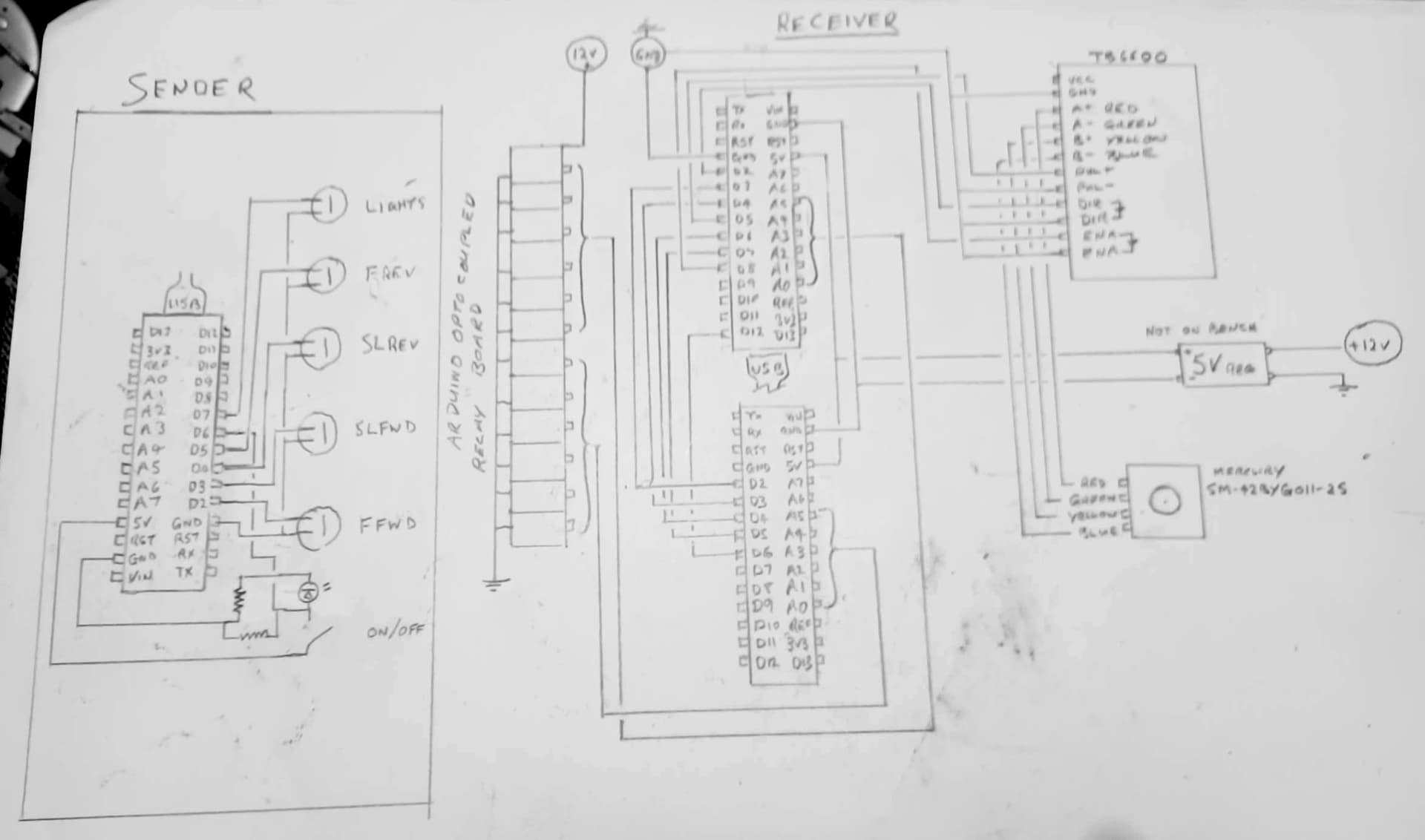
Here is the circuit diagram for Receiver (clock) and Sender (5 Buttons and one switch). The switch is intended to turn out the lights and stop the clock.
regards
Your switch wiring should be ok, you have a pull-down to ground.
See my reply #32, you are sending the “clock” code with both the HIGH and LOW state of the switch, and never sending the “off” code.
1 Like
Just realised given the rating of the new stepper motor 1,7 A I should set the current on the TB6600 controller to 1.5 A with PK 1.7 A (dip switches).
Stepper Motor: Bipolar, 200 Steps/Rev, 42×38mm, 2.8V, 1.7 A/Phase
[Mercury Motor SM-42BYG011-25]
But I am driving the controller with 12 V so is that a problem for this 2.8V motor?
regards
A bit late to change strategy at this point, but with nRF24L01 radios on all the boards, you don’t need to run wiring between the two boards on the receive end.
1 Like
I just solved my mysterious clock send signal from the remote sender when switched off. It was just a code error. So now the real problem is the "slave" Arduino is not receiving data from the clock Arduino!
This is the offending code line
void loop() {
  // Read pin D5 (High = Data available, Low = No Data):
  // Data is read on D2, D3, D4
  // Read pin D6 to turn light on or off
ready = digitalRead(5);  // D7 on the clock

if (ready == HIGH) {  // read a 4 bit binary number and convert to integer
  b1 = digitalRead(2);
  b2 = digitalRead(3);
  b4 = digitalRead(4);
  set = digitalRead(6); // switch ON = HIGH / OFF = LOW
  num = b1+2*b2+4*b4;
  light = "A" + char(num);  // light number {A0 to A5}
  Serial.println(light, num);
With the clock switch OFF the clock chip sends data to the slave on pins D3, D4, D5 and sets D5 HIGH to initiate a read of the data. But this code does not get executed? Is there a problem with "ready == HIGH" ?
regards