I’m building a theatrical prop - a birthday cake with six simulated candles.
The six candles draw 19mA max apiece. They’re driven by random PWM, so on average draw less. A seventh LED is used as a status indicator and draws 6mA. It flashed for 1/2 second with a 50% duty cycle. The total is 120mA, well below the pin draw and total draw limits.
D3, D11 & D12 don’t work.
D5, D8, D9 & D10 are working as expected.
Is there a limit or special initialization required? In setup(), all pins are set to OUTPUT.
I have another Nano as a backup. But if I’ve done something wrong, I don’t want to destroy the last device I have.
There’s only a day or two before this has to be delivered. Any advice will be greatly appreciated. Thanks in advance
please post circuit diagram or pictures and full code... I assume you're not using digitalWrite() like your example code... is it possible it's not wired correctly? Is there more going on than lighting LED's?
On digital pins, analogWrite() with a value below 128 is tha same a digitalWrite(LOW) and analogWrite() with a value above 127 is tha same a digitalWrite(HIGH).
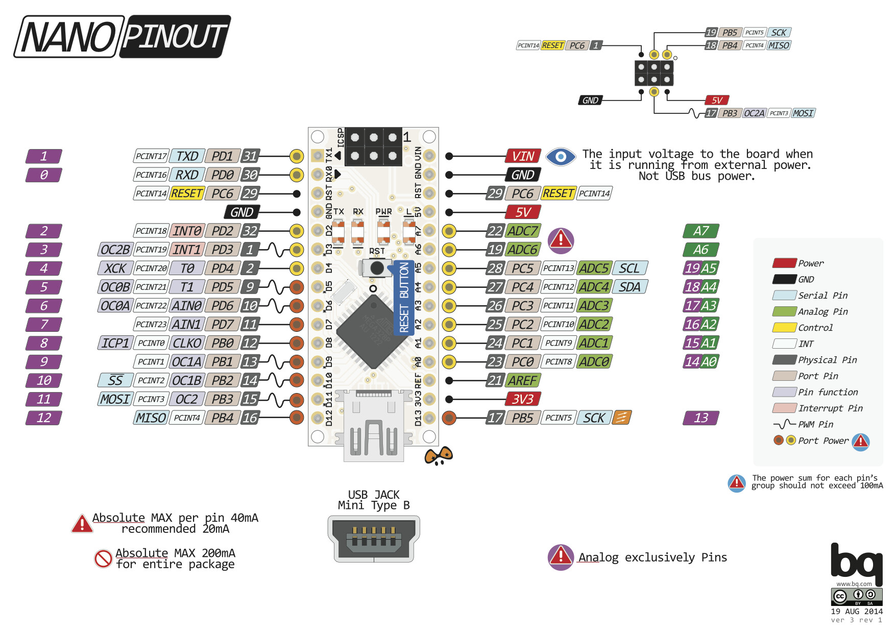
Wait a minute! Go back to my first answer to you. 3,5,6.., are the numbers of the DIGITAL pins, not the actual pin numbers. You are referring to D3,D5,D6...
Look at a picture of the Nano. Pin 3 is an INPUT and used to reset the processor. I doubt strongly that it is a PWM pin. If you look, D3 maps to pin 6. Since pin 3 cannot be an output and it so happens that D3 is a PWM output and is in pin 6, I’m still unconvinced.
That is my EXACT test code. Nothing else is happening. It’s powered through the USB connection. It is lighting ONE LED (or not, since that’s the problem). Wiring is EXACTLY as I described, except I didn’t mention the USB connection. The LED works by itself. It’s a brand new Nano.
The original circuit did have two additional LEDs & current limiting resistors that did not work and four LEDs and current limiting resistors that do work.
I simplified the environment as much as possible. So, yes, it’s a USB cable, Nano, five lines of code, an LED and resistor pair. It works on four pins; doesn’t on three.
Ok, that last pinout is different than the one I posted. I had hoped for this. Meaning, an easy to fix scenario would be based on a pinout confusion. I’ll test it tonight.
It's very unusual to talk about pins on a board like Uno or nano other than by the numbers printed on the board.
I have never once, in 7 years of playing with Arduino, referred to a pin by any other number than those printed on the board.
So look at the text in the pic you linked at circuitstoday: the ones labelled "PWM" (which on an Uno are marked ~) are D3, 5, 6, 9,10 and 11. Those are the numbers in the page I linked, and are the numbers used in pinMode() and the various write and read commands.
Not disagreeing with you at all. I’ve only run into this with the Nano. But, just for discussion, A0 is printed on one pin of every Arduino I’ve worked with. What pin is A0? It’s not pin 0.
(Sorry for the delay. I’ve been a member here for many years, and suddenly the forum software thinks I’m a noobie. Five minute limit between posts. Ridiculous)