Capacitors on DIY PCB - which ones and where to place

Hello,

I'm working on an aquarium computer project. And I'm almost at the point of going from breadboard to PCB. I'm thinking of making my own PCB for that, and I've tried to design one with Fritzing.

It will be connecting my Arduino Mega, the ESP8266-01 wifi-module (with a logic-level-converter, prog-uart switch and reset button), an EEPROM adapter, an SD card reader module, RGB drivers, a buzzer, DS3231 RTC, connection for my pumps, relay-board (and leds), temperature meters, 2 dc-dc converters, and some extra 5v and 3.3v headers.

So far so good, but after reading some tips for the use of capacitors in combination with the ESP8266 wifi-module, I figured it would be a good idea to add some. So I've added a ceramic 0.1uF close to the ESP8266, and a 47uF electrolytic aluminium capacitor in between my 12->3.3v dc-dc converter.

But this got me thinking: Wouldn't it be a good idea to put in some more capacitors. So I've started reading on the use of capacitors, but so far I still don't have a clue of which capacitors I should use, and where to place them...

So I'm hoping that someone here can help me...
Should I, for instance, place another 47uF cap after the 12->5v converter. And some before the dc-dc converters? Or should I use different capacitors?

The two voltage regulators need both an input and output capacitor. It should tell you the values in the data shee. Make sure the data sheet is by the same manufacturer as the actual part because actual requirements do differ.

Also I would put a 100uF across the 12V inputs to each led strip.

Add top & bottom layer ground plane, vs distributing it via traces.
Post your schematic as well - not the picture of all the components.

Are those switching (buck) voltage regulators, or linear ones? If switching, they should already have a filter cap on them, and you probably don't need another one. If they're linear, use the type and value of capacitor specified in the datasheet, one on input, one on output - some linear regs are very picky, others aren't, and most care what kind of cap (electrolytic, tant, or ceramic) is used. You may choose to add additional electrolytic caps to the output, but I recommend it only if you've determined that there is unacceptable ripple on the output of the regulators. If using a linear regulator with long wires/traces between the 12v supply and regulator, I'd throw on an electrolytic cap on the input (say, 100uF to 470uF) for good measure.

Every digital IC should have a 0.1uF ceramic cap across supply right next to it minimizing length of traces. Unless the datasheet specifies some other value. Even when the datasheet doesn't spec any decoupling cap, you probably ought to use one. For ESP8266 modules, especially the ESP-01, I would use a 10uF ceramic, not a 0.1uF one - the module already has 0.1uF ones; what it seems to lack is a larger value decoupling cap (the sudden current surges that that module can pull are sort of shocking - it can go from 30mA to 300mA in an instant when it transmits.

And - yes, use a ground ground plane (aka pour) on both sides, except close to where the antenna of the ESP8266 would be; ideally you don't want any copper right around where it's antenna will sit, as that can reduce wifi performance.

You got good information on caps, I would also have all the header pin 1 in the same direction. ( all the horizon either left or right and all the vertical top of bottom).

A couple of things fascinate me about the general design here.

The ESP-01 alone contains vastly more computing power than an Arduino Mega including EEPROM capability, and I am wondering why you would use a Mega rather than a Nano? It would seem the only reason for using an Arduino at all would be to provide lots of pins, but a WeMOS D1 Mini and a couple of shift registers should be able alone to fulfil all the requirements.

In any case, it has been mentioned that there should be no fill under the ESP-01. Better still, there should be no traces - nothing - under the ESP-01; the best place to mount it would be in an open corner and/ or overhanging the PCB.

Thanks a lot for al the input and ideas. Helps a lot, because a lot of this is new for me.

Yes, I'm using buck converters (the mini-360), and it does seem like the already have capacitors.

DrAzzy:
Every digital IC should have a 0.1uF ceramic cap across supply right next to it minimizing length of traces. Unless the datasheet specifies some other value. Even when the datasheet doesn't spec any decoupling cap, you probably ought to use one.

Does this mean I have to check the modules I'm using, to see if they have caps next to the IC on it? And if not, place one 0.1uF ceramic cap close to the vcc and gnd pin?
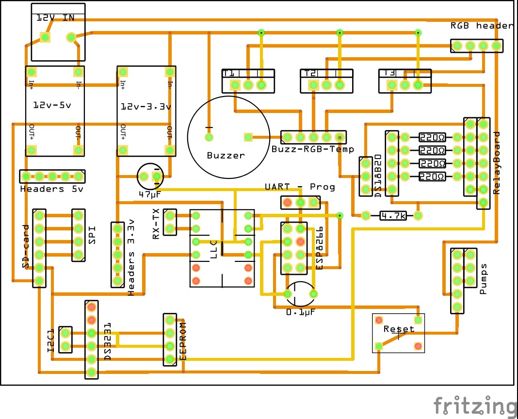
As far as I can tell only the relay module and the EEPROM adapter don't have there own caps...

DrAzzy:
For ESP8266 modules, especially the ESP-01, I would use a 10uF ceramic, not a 0.1uF one - the module already has 0.1uF ones; what it seems to lack is a larger value decoupling cap (the sudden current surges that that module can pull are sort of shocking - it can go from 30mA to 300mA in an instant when it transmits.

When I google "ESP8266 capacitor" I see a lot of guys advising to add in a 0.1uF AND bigger cap like the 47uF electrolytic. Some even say to use a 470uF. So I don't understand why you are telling me to drop both and add in a 10uF ceramic cap. Can you explain this to me? (as you can see I'm obviously a bit clueless with electronics)

DrAzzy:
And - yes, use a ground ground plane (aka pour) on both sides, except close to where the antenna of the ESP8266 would be; ideally you don't want any copper right around where it's antenna will sit, as that can reduce wifi performance.

The ground plane sounds like a good idea, but its new for me, so I will start look in to this and try and find out how to implement this. (I will keep in mind to put the ESP on the edge of the PCB)

Paul__B:
A couple of things fascinate me about the general design here.

The ESP-01 alone contains vastly more computing power than an Arduino Mega including EEPROM capability, and I am wondering why you would use a Mega rather than a Nano? It would seem the only reason for using an Arduino at all would be to provide lots of pins, but a WeMOS D1 Mini and a couple of shift registers should be able alone to fulfil all the requirements.

In any case, it has been mentioned that there should be no fill under the ESP-01. Better still, there should be no traces - nothing - under the ESP-01; the best place to mount it would be in an open corner and/ or overhanging the PCB.

I guess you're absolutely right, but I started this project with an Uno, ran out of pins so continued with the Mega and later on I discovered the existence of the ESP8266 and decided to add this to my project as well for communication with the app I'm also building.

Looking at the PCB it appears you're using modules for all components, that you plug in, rather than the bare chips. Normally the capacitors are in place already on those modules, and there's no need to add any more on your PCB.

Also make sure you have enough space to plug in all those modules. The EEPROM and DS3231 appear to be too close together, but it depends on the size and shape of the actual modules you have.

Hi,
Can I suggest you thicken up all your tracks, you have bought a PCB covered in copper and you are going to pay someone to take it away.

Try and leave as much copper on the board as possible, all your tracks could easily be twice as wide.
Especially any gnd and power supply tracks should be thicker.
How much current will the RGB LEDs consume?

Put some LEDs on the PCB to show your power supplies working, they only need to use 5mA for this application.

Ground planes are good idea and you keep copper you have bought on the board.

Also put your PCB name in copper on the board, and label + and - in copper on the copper side, it will help with any troubleshooting you may have.

Can you please post a copy of your circuit, in CAD or a picture of a hand drawn circuit in jpg, png?

Tom... :slight_smile:

wvmarle:
Looking at the PCB it appears you're using modules for all components, that you plug in, rather than the bare chips. Normally the capacitors are in place already on those modules, and there's no need to add any more on your PCB.

Also make sure you have enough space to plug in all those modules. The EEPROM and DS3231 appear to be too close together, but it depends on the size and shape of the actual modules you have.

Ok, I thought so but your confirmation puts my mind at ease. Thanks.
The modules should have enough space, but I will check everything on paper, just to make sure.

TomGeorge:
Hi,
Can I suggest you thicken up all your tracks, you have bought a PCB covered in copper and you are going to pay someone to take it away.

Try and leave as much copper on the board as possible, all your tracks could easily be twice as wide.
Especially any gnd and power supply tracks should be thicker.
How much current will the RGB LEDs consume?

Put some LEDs on the PCB to show your power supplies working, they only need to use 5mA for this application.

Ground planes are good idea and you keep copper you have bought on the board.

Also put your PCB name in copper on the board, and label + and - in copper on the copper side, it will help with any troubleshooting you may have.

Can you please post a copy of your circuit, in CAD or a picture of a hand drawn circuit in jpg, png?

Tom... :slight_smile:

Good points! Will do that... Thanks for the input.
I'm using 3.5meter RGB 5050smd ledstrip, so I guess 4 amps in total?

I have already posted a image of my circuit, haven't I?
Will post a new one soon.

Coos:
I'm using 3.5meter RGB 5050smd ledstrip, so I guess 4 amps in total?

Don't guess. Look up the specifications of your particular strip, as it depends on the number of LEDs per meter and the supply voltage.

Make sure your buck converter can do that current twice over (it NEVER hurts to down rate them, if anything it saves a lot of heat).

Make sure the MOSFETs(??) T1, T2, T3 can handle this current comfortably, and won't produce too much heat (check ON resistance, or if it's a BJT the forward voltage drop, to calculate heat production).

Use at least 1 mm, preferably 2 mm or even thicker traces for the power lines to these components. Or even thicker if you can.

Ground/power planes are very convenient as well. I usually put a ground plane on the back, power plane on the front. The two form a capacitor, which also should help in reducing noise.

I have already posted a image of my circuit, haven't I?
/quote]

I've only seen the PCB. Hope you have a proper, well readable circuit diagram as it's done with Fritzing which doesn't make me hopeful.

wvmarle:
Don't guess. Look up the specifications of your particular strip, as it depends on the number of LEDs per meter and the supply voltage.

Make sure your buck converter can do that current twice over (it NEVER hurts to down rate them, if anything it saves a lot of heat).

Make sure the MOSFETs(??) T1, T2, T3 can handle this current comfortably, and won't produce too much heat (check ON resistance, or if it's a BJT the forward voltage drop, to calculate heat production).

Use at least 1 mm, preferably 2 mm or even thicker traces for the power lines to these components. Or even thicker if you can.

Ground/power planes are very convenient as well. I usually put a ground plane on the back, power plane on the front. The two form a capacitor, which also should help in reducing noise.

I have already posted a image of my circuit, haven't I?

I've only seen the PCB. Hope you have a proper, well readable circuit diagram as it's done with Fritzing which doesn't make me hopeful.

There is no buck converter between my power supply and led strip, it's powered directly by a 12v power supply, which is also feeding the buck converters. And yes, I'll make sure it can provide enough current.
And I've also made sure the MOSFETs (IRLB8721) can handle it.

I guess you're talking about a schematic; I'm working on that. Will post it when I'm ready...

How can you possibly design a PCB without drawing a schematic first??

Here is the schematic.
It's my first, so I hope I've done things the right way...

Hi,
Sorry but you need to show ALL your components.

Where is the Arduino?
What does the ESP8266 do?
Where is the EEPROM?
What are R2 to R5 doing?
DS3231 is a RTC AND EEPROM.

That diagram may be okay if you are making a PCB, BUT to show circuit signal flow in my opinion they are hopeless.
You don't need to show so many power supply headers!!!!

I have to say its one of the cleanest Fritzy schematics I have seen, well done, but it conveys little about your project components.

Sorry.. Tom... :confused:

Hi Tom,

Thanks for your honest reply.

I realise that this is not a complete diagram, just one for making my PCB. Because I have everything working via my breadboard, and making a complete schematic is a lot more complex than this one, I considered it not necessary to make a complete one.

I started this thread because I had questions about the use of capacitors. I hope I've implemented al the tips about them in this circuit, the right way.
(I just saw that the R7 resistor has a wrong value. I will make that 600Ω.)

As for your questions;
The ESP8266 is a wifi module which will communicate with the Arduino via the TX-RX headers (serial communication). The EEPROM is on a adapter I will connect via the headers I reserved for this. The resistors R2 to R5 are there for the LEDs I'm going to connect to the headers on the left side of them (the labels are accidentally overlapping each other in this image). This is also the reason why I have put those relay headers on this board.

Another question I have right now is about the ground plane. It was suggested that I put one on the bottom AND top layer. Why should I do that? Is one on the bottom layer not enough?
I'm designing a new PCB with all the ground traces on the bottom layer, and all the power and signal traces (except one) on the top (as thick as possible). So I figure it would be best, and easiest to put a ground plane on the bottom layer, and copper labels on the top.... Does that make sense to you?

TomGeorge:
Hi,
Can I suggest you thicken up all your tracks, you have bought a PCB covered in copper and you are going to pay someone to take it away.

PCB manufacture uses several plating and etching stages - its very different from home etching, and the metals are recycled. The amount of copper will be reflected in the pricing for some houses.

Try and leave as much copper on the board as possible, all your tracks could easily be twice as wide.
Especially any gnd and power supply tracks should be thicker.

Logic signals should be narrow traces (low capacitance), power and ground wider (for low inductance).

How much current will the RGB LEDs consume?

Put some LEDs on the PCB to show your power supplies working, they only need to use 5mA for this application.

Ground planes are good idea and you keep copper you have bought on the board.

Also put your PCB name in copper on the board, and label + and - in copper on the copper side, it will help with any troubleshooting you may have.

Can you please post a copy of your circuit, in CAD or a picture of a hand drawn circuit in jpg, png?

Tom... :slight_smile: