Hello….. A total noob here looking for some advice in regards to capturing the status of a TTL IC logic gate with a Arduino.
I have an old arcade game from the 1970’s that has an issue with some lights that don't want to illuminate due to a board issue that I have been unable to track down. With a logic probe, I was able to find the SN7046 IC that toggles from high to low on it’s output leg of a logic gate, which when inverted by the IC, should light the lamps if the board was functioning correctly.
I figured that this would be a perfect task for an Arduino to handle. Simply tap into the IC’s output pin for the lamps via a wire and attach the other end to an input pin on the Arduino, and when the signal toggles from high to low, I’ll have code in the loop light a replacement LED strip for the required time.
But I can’t seem to be able to capture the signal change on the Arduino input.
Any help would be greatly appreciated. Thanks for any replies in advance.
Here is my really basic code, using the onboard LED as a test (I'll work on LED strip logic after getting the code to register the signal)
> // the setup function runs once when you press reset or power the board
> void setup() {
>   // initialize digital pin LED_BUILTIN as an output.
>   pinMode(LED_BUILTIN, OUTPUT);
>   pinMode(7,INPUT);  //pin hooked to IC on main board of video game via wire
> }
>
> // the loop function runs over and over again forever
> void loop() {
>   if (digitalRead(7) == LOW)  //if we detect a change in the signal from the video game
>   {
>   delay(2500);                       // wait for a 2.5 seconds
>   digitalWrite(LED_BUILTIN, HIGH);   // turn the LED on (HIGH is the voltage level)
>   delay(5000);                        // keep lights on for 5 seconds
>   digitalWrite(LED_BUILTIN, LOW);    // turn the LED off by making the voltage LOW
>   }
>   else
>   {digitalWrite(LED_BUILTIN, LOW);} // probably not needed, overkill
> }
Well now, the 7406 clearly does not drive the lamps directly as it simply cannot.
You need to give us some schematic details of how it is connected and to what.
To interface antique TTl logic to CMOS such as an Arduino, you generally need to use a level converter such as the 74HCT14 Hex inverter, however for an open-collector chip you only need a pull-up - say 10k.
Unless it is connected to something else - in which case you must explain what that is.
Thanks for the reply. I misspoke with my original post. On the 7406, we're dealing with pair 13(input from other IC's on the board) and 12(output to lamp controlling part of the board's circuitry). Both are working as expected and are handling the signal correctly from the board. When activated, pin 13 toggles from high to low, and pin 12 inverts the signal and outputs high.
My lead is indeed attached to pin 13 since I wanted to avoid any possible impact from the lamp side of the gate. I apologize for the error.
Thanks for the reply.... you are 100 percent correct in the fact that the 7406 is telling other circuitry to handle the lighting of the lamps (which for the life of me I cant figure out what is wrong). This seems to be the last part of the line where I'm getting what I consider a good, repeatable outcome. Hence my wanting to tap into the results coming from the 7406.
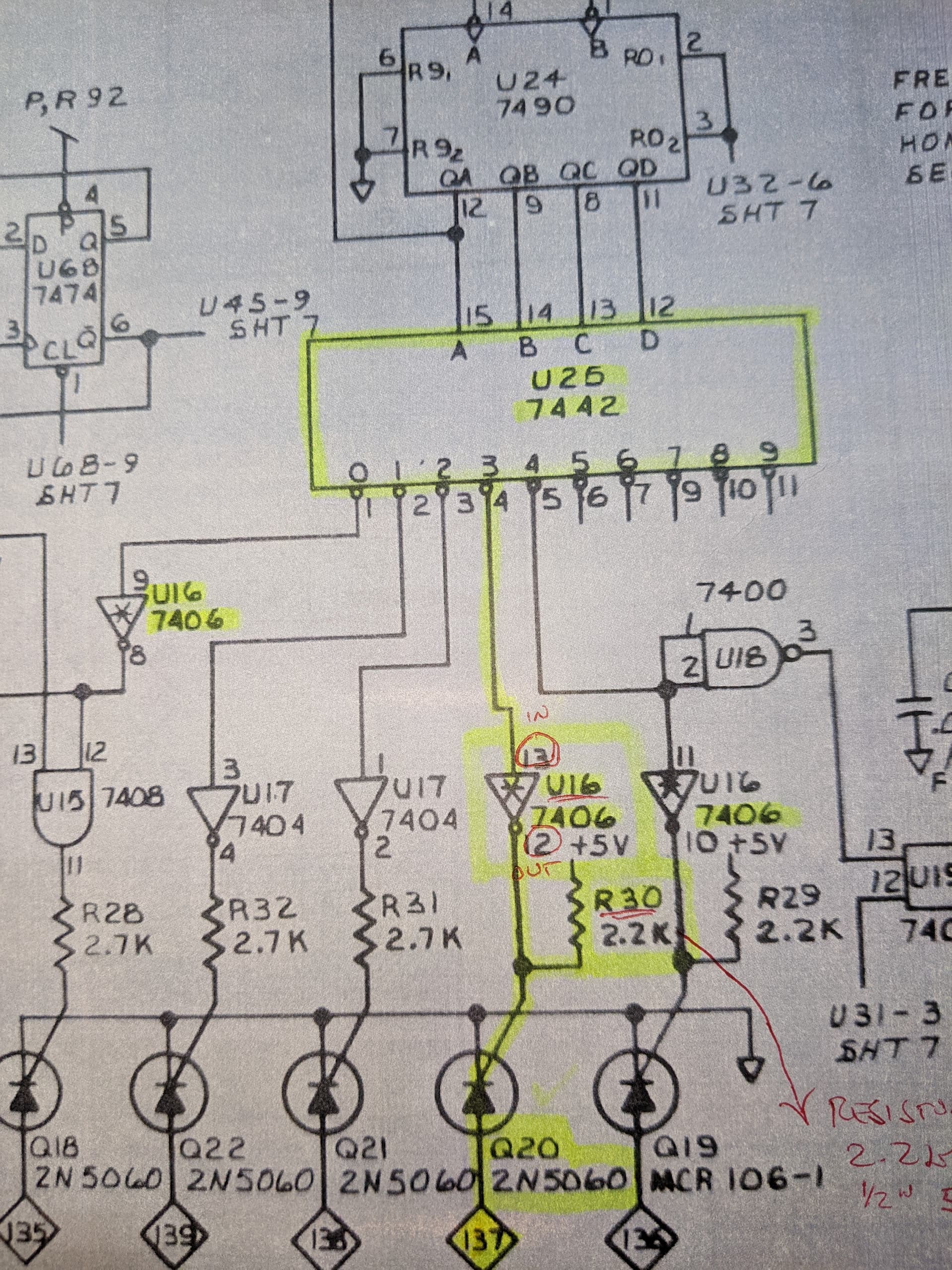
Here's the schematic for the part of the main board that we're working with. U16 is the IC we're working with. I hope this helps.
As you've probably already figured out, my electronics expertise is very limited so please bare with me as we work through this. I really do appreciate everyone's help and I've had fun working with the Arduino. Man, these little things can do so much.... it's crazy! What I'm wanting to do here with it seems like it should be simple, but I think I may be underestimating it just a tad.
Thanks again, and thanks in advance for any future replies.
I could identify all the chips without looking at a data sheet! Those were the days...
The 7406 only happens to be used here as the standard chips (7404, 08) for other lamps indicate. The 7406 already have pullups on board but the following thyristors destroy the logic signal levels.
At the input pins you should get pretty signal levels from the decimal decoder 7442 output. If not you can use optocouplers (to +5V) to convert and isolate the 7442 outputs from your circuitry. Standard TTL can sink 16mA (fan out 10) so that abusing a few mA for the optocoupler should do no harm.
But after all I'm wondering why you have problems with the signals at all. If it's only that specific signal you also can catch the 7442 decoder inputs (A, B, C, D) and decode the '3' state.
Good deal.... so it sounds like I'm on the right track in regards to where I've tapped into the circuitry since I'm on 13.
So...... could it be as simple as not having a common ground from the Arduino back to the main board in the game? I do not have one established. My only connection from the game is the wire to the pin on the 7406.
Damn..... I was thinking this was needed to start with, but got ahead of myself and it didn't click until a few minutes ago that it wasn't there.
I would assume that there are some posts out there in regards to hooking a ground from the main board on the game to the Arduino? Or could you give me a quick recommendation as to what pin to hook it up to on the Arduino?
A ground is upon what are standing all related components.
You can connect the ground planes of the boards at one of the dedicated connectors. With long wires a twisted pair for each signal line may be preferable, ribbon cables are fine for that solution.
Thanks for the replies. I'll try to get the ground in place this evening and retest.
As for the problem with the game's main board, it's strange in the fact that everything seems as if it should work. I've even went as far as to replace the 7406 though I didn't think it needed it, and also the 2N5060 which seemed to show signs of being a little bit out of spec. Neither helped. I also swapped the two resistors (R29 and R30) to see if the issue moved from one output to the other, but no change so I'm good there also. There's really nothing else between the 7406 and the output pin (137) to the lamp board. I wonder if it may be some sort of short with the lamps? If I go across the output pins on the main board with the game on (pins 135 - 139) using a logic probe, I get signals on all pins other than 137, so maybe something on the lamp board side is causing the issue? I get continuity back to pin 137 on the board from the lamp sockets when testing with a multimeter, so all solder joints are good.
Like the missing common ground, it's probably something really simple. LOL! My lack of expertise is the biggest issue here.
Something that old might have developed an open solder joint. See if it makes any difference by gently flexing the board while you think you should be getting a lamp on. A through-hole connection like on logic ICs can break and be very hard to see. Get a strong light and a magnifier and closely inspect the solder side of the board in the suspect area. Sometimes you can see the pin move or a gap open up by wiggling the pins on the solder side with a pair of tweezers while under the light and magnifier.
FYI,
not to state the obvious, but ALL digital signals consist of 2 wires; signal and GND with the GND
being common with the device the signal is interfacing with. It would not matter what kind of
signal it is, even an analog input or output. It would still require a common GND.
The fact that you even posted for this issue suggests that maybe you should read this
It is the book that some have referred to as the TTL BIBLE.
Practically everyone who has ever used TTL at some point is familiar with it.
While it is true that some consider TTL to be obsolete, there nevertheless remains many
TTL circuits still in operation today. The information contained in the book amounts to
a primer in digital circuitry. Most of what is in the book is still valid, however the FAN OUT
and almost all other specs are different for the newer digital families like LS, HC etc etc etc.
I would recommend it strongly.
Yes, I should have caught the missing common ground way sooner. As stated multiple times, I am completely new to this level of electronics, and a total noob in regards to the Arduino.
I will say that it's been interesting for sure to learn about how some of the TTL stuff works. I had no idea about IC's, logic gates, inverted output, logic probes..... and I've been able to save an old game from being tossed onto the scrap heap. The final "fix" with using the Arduino to simulate the missing light sequence will make it 100% fully functional.
I hope to not need to dig any deeper into the IC's but if I ever do, I'll be sure to circle back to the book you've mentioned. I appreciate the reply.
As DrDiettrich explains, the 7406 is not being used to generate a logic level at all. When enabled (a HIGH on its input), it pulls down the thyristor gates and prevents them from firing.
When disabled by the corresponding 7442 output pulling it LOW as the single one selected, the 7406 releases its output and the 2k resistor fires the thyristor. But the thyristor fires at about 1.8 V on the gate which is still a logic LOW, so you will simply not read it with a logic device.
Unless you actually propose to disconnect the 7406 from the circuit, which clearly you do not, there is no point looking at its output. If you actually want to monitor the logic switching, you can monitor the input to the 7406 from the 7442. However do take note - these are TTL devices and the logic levels are not compatible with CMOS such as 5 V Arduinos, so you need to use "74HCT" devices to interface it to any 5 V logic you wish to use as I explained in #3.
But you need to completely forget about the 7506 outputs.
Paul, so are you saying that I can replace the 7406 with the 74HCT that you linked to in #3 and that would then give me a signal that the Arduino can read?
Thanks for the help and info. I need all I can get. LOL!
If you want to monitor the operation of the 7442, just connect its outputs to inputs of a 74HCT14 in parallel with the assortment of 7404, 7406 and 7408s. You must use the same ground and 5 V supply. Of course, if monitoring with an Arduino, you could monitor the inputs to the 7442 instead.
You have caused me to look more closely at the circuit. the 7406 means that the lamps turn on when the 7442 select them. The 7404 does the same as does the 7408 in a slightly different manner; there is some "fancy footwork" afoot here using just part of one IC and part of another, with each IC being used for multiple different circuit functions.
Ok, with a ground established on the Arduino back to the main board on the video game, I tested my setup and as you've stated, it seems that I'm not able to register the signal change on the Arduino.
Some noob questions for you (or anyone else who wants to share some knowledge), with my goal being to not impact the existing circuitry on the main board that is working in any way unless it's absolutely necessary -
How would I go about integrating the 74HCT14 in parallel with the 7442 and 7406? Since the 7442 controls multiple IC's other than the one we're dealing with, how would that work?
Since I'm only concerned with the signal from the 7442 on its output pin 3 (as shown on the schematic), can we simply isolate that and route it through the 74HCT14 and not impact any of the other outputs?
The prior hints by others regarding the use of an octocoupler sounds like it may be a possibility also? Again, if we try to integrate an octocoupler into the equation in an attempt to grab the output on the 7442's pin 3, would that possibly be a simpler route to go?
As usual, everyone's help here, along with your tolerance of my ignorance, has been really appreciated and I cant thank you all enough for your time and effort.