Ah ok
I’m not sure if I was clear but the gauge is digital not old analogue.
Anyway I’m just putting my ideas about to see what people think.
I like simple so I start simple and get more complicated as needed.
Thanks for your help it’s appreciated
Yes but it is responding to an analog signal. Or do you have a way of controlling it through a digital signal ?
Not sure about that. I do know that the gauge moves up and down as the voltage changes.
I’m going to take some voltage readings at various points on the scale and see what that tells me.
With that information plus the information from the sender at those points I might just be able to send the right amount of volts to the gauge with some kind of calculating software?
Again I’m not sure at all but this is my brain working through the steps to get the correct voltage to the gauge.
Maybe doing a reading every 30 seconds and changing voltage out at the 30 second intervals (keeping at last voltage until the next reading comes in.) that should help keep the gauge smooth as well.
Well that’s what my brain tells me. Might not work that way.
Sorry I have Asperger’s so I soak information up and see wildly different ways of fixing a problem that normal people do!![]()
I have plugged one of these into an output of a truck with an ecu(as in tapped into one of the pins that is for temp gauge) and it works from that so I’m guessing (I do a lot of that!) that it responds to a digital output as well.
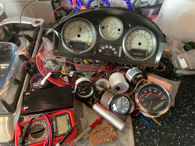
I have all sorts of gauges here problem is that I can’t get a reliable supply of gauges that turn in the correct direction for my gauge cluster!
The background is done the housing for all of it is done the fuel speedo and revs are done. The temperature gauge is the problem.
I have 50 units coming from China as a special order that do work properly, however I need to use up 20 or so gauges that go the right way but don’t work at the right ohm rating. I’m an old school man in a shed fixing/creating things (well kitchen but you get the idea) type person. Lots of brilliant ideas have come from sheds or kitchens🤣
But you have a schematic with the solution ! This is what gets me. Why do you want to complicate things with an MCU and it's power requirements and connections, when there is an analog solution that, if you take a proper look at it, really isn't all that complex and doesn't contain all that many parts.
There are some parts on there that are not fully clear to me what their values should be (R1 & R1a & R2), but i would just order the zener diodes and the LM358 (i have one of them actually, but you probably don't, but a LM324 could be used as well) and maybe the transistor (though i would try with a BC547 that i do have) and set the thing up on a breadboard and see if i can get it working properly, without going through all the complications of using an MCU and having to program it etc.
Anyway, that is my advice and if you want to pursue a different avenue, i'll leave you to it.
Yes but i said already, you can only send PWM voltage, you will still need to filter that. Not only that, what you actually want is to create a 'variable-resistor' which you can control from a MCU. I am not saying it can not be done, i am just saying that it will be a lot of work, and more expensive, and in the end, probably less reliable.
In a way i see no upside to your plan, and a lot of downsides.
Thanks for being honest about my plans short comings! I have to work these things through to the end to stop my mind going into overdrive.
Seems I’m probably going to fail or maybe hit a dead end but n this. I just thought over 20 or so units software rather than old fashioned electronics might be the answer.
As always thanks
I’ve made the circuit I have all the parts I just like trying different things.
If I can get an MCU working it opens up other things as well
This topic was automatically closed 180 days after the last reply. New replies are no longer allowed.

