hi guys hope you are doing well,
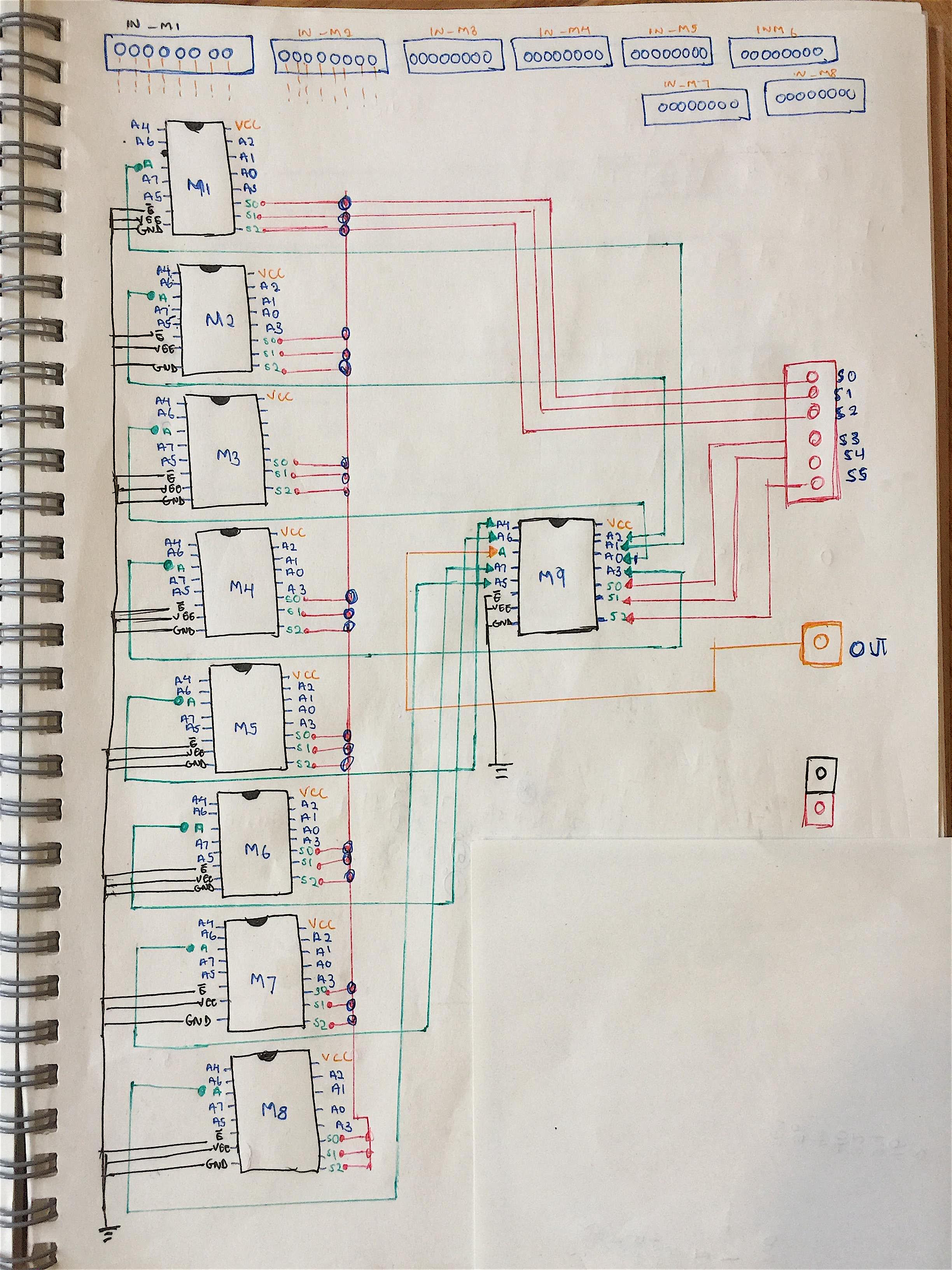
i need to cascade a 256:1 milteplexer using the 16:1 for analog readings.
for the hardware its not a big deal, but for the code i need some help in the mapping.
will somthing similar to this work for me? (this is a 64:1)
thanks in advance.
int M_S0 = 2;
int M_S1 = 3;
int M_S2 = 4;

int S_S0 = 7;
int S_S1 = 6;
int S_S2 = 5;
int analogPin = A0;
int Z =0;
int MUX64[64] = {0};

void setup() {
      // CONFIGURE ADDRESS PINS
    pinMode(M_S0, OUTPUT);
    pinMode(M_S1, OUTPUT);
    pinMode(M_S2, OUTPUT);
    pinMode(S_S0, OUTPUT);
    pinMode(S_S1, OUTPUT);
    pinMode(S_S2, OUTPUT);
    pinMode(Z, OUTPUT);
  Serial.begin(9600);

}

void loop() {

   // LOOP THROUGH ALL THE ADDRESSES OF THE MASTER
    for (int i = 0; i < 64; i++) {

    digitalWrite(M_S2, HIGH && (i & 0b1000000));
    digitalWrite(M_S1, HIGH && (i & 0b100000));
    digitalWrite(M_S0, HIGH && (i & 0b010000));
    digitalWrite(S_S2, HIGH && (i & 0b000100));
    digitalWrite(S_S1, HIGH && (i & 0b000010));
    digitalWrite(S_S0, HIGH && (i & 0b000001));
    delay(1);

    Z = analogRead(analogPin);


    Serial.print("Input ");
    Serial.print(i);
    Serial.print(": ");
    Serial.print(Z);
    Serial.println(" v ");
    delay(100);
}

}
The code depends on your exact circuit.
If you wire 16 multiplexers in parallel, you need 16 chip select pins - Arduino Mega?
Otherwise add a 1:16 decoder for chip select by only 4 bits (pins).
To me, it looks like your code is basically correct. I have no way to test it. I think it's (or - it could be) 8 selector pins - 4 for the one root mux and 4 for all 16 of the leaf muxes (address pins wired in parallel). So if you can find a way to locate the pins on the same port you could just write 'i' to the port, instead of all of that code.
This seems odd
digitalWrite(M_S2, HIGH && (i & 0b1000000));
to me it is just
digitalWrite(M_S2, i & 0b1000000);
because of the way HIGH and LOW are defined. digitalWrite() actually does
if (val == LOW) {
to determine how to set the port. This does guarantee that anything that is "not LOW" will set the port output. That would be my flimsy justification for the simplication above. This implicit guarantee is the result of the fact that a zero is bit-agnostic, in the sense that when it is used as a boolean 'false' and contains multiple bits like a byte does, there is no representation of zero that considers any of the bits differently (if one is 0, then they all are).
Note also that this addressing can be sparsely populated, i.e. you could use say, one root mux and 4 leaf muxes. If you make the right pin mapping (binary integer) you can achieve contiguous direct addressing of inputs from 0 to 63. In that case the leaf muxes use 4 bits and the root mux uses 2. In such cases you have other choices of root mux such as CD4051B.
16 CMOS inputs in parallel have a very large total input capacitance. It's worth looking at the driving circuit to ensure that it can drive such a heavy capacitive load.
@cherifdekari
The evaluation of your logical AND is from left to right; HIGH will always evaluate to true on an Arduino so after that it will evaluate i & 0b1000000 which will return a number.
The better way
digitalWrite(M_S2, (i & 0b1000000) == 0b1000000);
(i & 0b1000000) == 0b1000000 will give you true or false and in Arduino land HIGH and true are both 1 and LOW and false are both 0 so it will work.
The purists probably want something like
digitalWrite(M_S2, (i & 0b1000000) == 0b1000000 ? HIGH : LOW);
This uses a ternary operator (obfuscated if/else) . If the condition evaluates to true, it returns HIGH as the second argument for the digitalWrite, if it evaluates to false it will return LOW as the second argument for the digitalWrite).
oky u all agree that HIGH && (i & 0b1000000) is odd; ill change it.
one more question Mr @sterretje to access to sensor 256 i need one more bit right? can we use 0b10000000 ? (4bits for each of the mux) how can i do this?
Each channel has a resistance and capacity, forming a low pass filter of degree 2 with chained multiplexers. Find out how much time is required for stable values after a channel switch.
@TomGeorge@Paul__B
thank you for your reply.
for the project its a home automation app using esp32 i may not use all the 256 but i want such a large number.
for testing the 4067, no not yet i just tested the 4052 ( 4 chanels) it was okey.
"AtoD conversion is not instant" i need one reading each lets say 10 secondes its okey.
can you answer my question #5. how to map the control signals i.é
0bXXXXXXX for 8 control signals.
thank you
Home automation sensors have to sit in many locations, and it's very hard and expensive to route analog signals through the building to the µC. That's why intelligent sensors with digital outputs are typically easier to use at less overall cost.