5.1 Introduction
1. In ATmega328P MCU, there is a UART Port (Fig-5.1) to transfer data in serial format (bit-by-bit) to PC using TXD (transmit data line) and to receive data in serial format from the same PC using RXD (receive data line). UART Port stands for "Universal Asynchronous Reception and Transmission" Port.
ATmega328P MCU-এর মধ্যে, UART নামে একটি পোর্ট আছে (ছবি-৫.১)। MCU, এই পোর্টের TXD লাইন ব্যবহার করে PC-র কাছে ডাটা পাঁঠায় ১-বিট করে করে; আর, RXD লাইন ব্যবহার করে PC-র কাছ থেকে ডাটা গ্রহণ করে ১-বিট করে করে। তাহলে, বুঝা গেলো যে UART পোর্ট একটা Serial Communication পোর্ট।

Figure-5.1: UART and SUART Ports of Atmega328P MCU
2. There is only one hardware/electronic UART Port (UART) inside the MCU. It is permanently engaged with the PC and with the Serial Monitor (Fig-5.4) for data input/output purposes and with the IDE (Fig-5.1a) for sketch uploading.

Figure-5.1a: IDE (integrated Development Environment) of Arduino Platform
3. If it is desired to exchange data between UNO and NANO (Fig-5.1) in UART protocol, then there is no more UART Port left. Under this circumstance, it is possible to create a software UART Port (SUART) (Fig-5.1) by which the two Arduinos of Fig-5.1 can exchange data serially. To create a SUART Port, the following codes are included in the appropriate places of a sketch.
#include<SoftwareSerial.h>
SoftwareSerial SUART(2, 3);  //SRXD = DPin-2, STXD = DPin-3 ; S stands for Software
SUART.begin(9600);      //SUART Port works well at this bit speed = bit/sec
4. In S/UART (SUART and UART) communication, data exchange takes place one byte (8-bit) at a time (byte-by-byte or character-by-character), which could be a natural binary number or an ASCII code of a printable character (Fig-5.2) of the English Language Alphabet (a-z, A-Z, punctuation marks like ! and others, special characters like $ and others). When ASCII codes are being transmitted and received, it is said that data exchange takes place character-by-character.

Figure-5.2: ASCII Codes Table
5. In Fig-5.3, it is shown how the ASCII code (0x41 in hex = 01000001 in binary) of character A travels over the TX-line of the UART Port. There is a 'START bit' (LOW), then the LSB bit, ..., and then 'STOP bit (HIGH)'. The parity bit is optional. These 10-bit (ignoring the parity bit) data is known as asynchronous frame; where: the frame length is 10-bit, the character length is 8-bit and the wastage of time is 20% (2/10*100).

Figure-5.3: Asynchronous frame for character A
6. In UART communication, Bd (Buad) refers to number of bits being transmitted/received in one second (bits/sec). For example: Bd = 9600 means that the bit transfer rate is 9600 bits/sec which ie equal to 960 (9600/10) characters/bytes per sec. (In fact, Bd and bit/sec are not the same things; only in UART communication they stand to be the same things. The discussion is beyond the scope of present context.)
5.2 Data Exchange among InputBox, OutputBox and UNO
1. Fig-5.4 depicts the layout of the Serial Monitor of Arduino Platform, which comes in when a click is made on this ![]() icon located at the upper-right corner of the IDE.
icon located at the upper-right corner of the IDE.
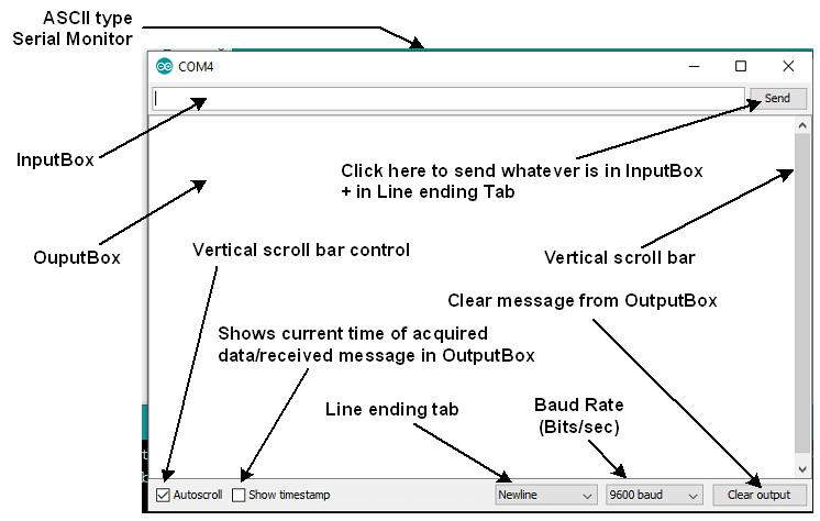
Figure-5.4: Layout of Serial Monitor
2. Connect UNO with the PC and select the Board and COMX Port as needed. Launch the IDE and bring in the Serial Monitor. Select 'No len ending' in the 'Line ending tab'. Focus the cursor (bring the cursor) in the InputBox (Fig-5.4) of the Serial Monitor. Enter A from keyboard of PC and then click on the Send button. As a result, the frame of Fig-3 will be travelling towards UNO over the TXD line (Fig-5.5).

Figure-5.5: FIFO type Serial BUFFer of Arduino Platform
3. When the frame of Step-2 arrives to UNO, the UNO is automatically interrupted; it (the UNO) goes to a side job (called ISR = Interrupt Sub Routine) and receives the frame; the START and STOP bits are discarded and then the ASCII code (0x41) of A is automatically saved into Location-0 of the unseen FIFO (first-in first-out) type Serial Buffer (Fig-5.5).
4. To bring out the ASCII code of A from the BUFFer and save it into a user variable, the following steps are taken:
(1) Check if the BUFFer contains data items by executing these codes:
byte n = Serial.available();
if(n != 0)   //BUFFer contains at least one data item; here the ASCII code of A
{
    //bring out ASCII code of A from serial BUFFer of Fig-5 and save into user variable
}
(2) Bring out/raed the ASCII code of A from BUFFer and save into a user variable by executing this code:
char x = Serial.read(); //x holds 0x41 = ASCII code of A;
5. To show the character (whose ASCII code we have got in Step-4(2) into OutputBox of Serial Monitor, the following code is executed:
Serial.print(x); //the data type of x must be char
The above code is converted to the following code in order to put the ASCII code (0x41) of A on the TXD line. As a result, A will appear on the Serial Monitor.
Serial.print(x);
==> Serial.write(0x41);  //A appears on the OutputBox of Serial Monitor
6. Exit the Serial Monitor and bring it again. Select Newline option in the Line ending tab of Serial Monitor of Fig-5.4. Enter A and then click on the Send button. Answer to the following questions:
(1) How many frames will be travelling towards UNO?
Ans: Two frames.
One frame for character A whose ASCII code is 0x41.
Second frame is for the Newline character whose ASCII code is 0x0A and the C- code is '\n'.
(2) Which location of the FIFI BUFFer of Fig-5.5 will hold the ASCII code of the Newline charcater?
Ans: Location-1.
(3) What will be the value of n after the execution of the following code?
byte n = Serial.available();
(4) Write codes to empty the BUFFer of Fig-5.5. (There will be no more data item in the BUFFer to read.)
Ans: ?
char x = Serial.read();  //X = 0x41 = the ASCII code of A charcater
char y = Serial.read(); //y = 0x0A= the ASCII code of Newline character
5.3 Questions and Answers
1. The following sketch is uploaded in the UNO. The word Arduino is entered in the InputBox of the Serial Monitor (No line ending option) and then the Send button is clicked. What charcaters (all the 7 charcaters of the word Arduino or a few of them) will appear on the OutputBox of the Serial Monitor?
void setup()
{
   Serial.begin(9600);  //hardware UART Port is active/enabled with a speed of 9600 bits/sec
}

void loop()
{
    byte n = Serial.available();
    if(n == 3)
    {
        char x = Serial.read();
        Serial.print(x);
        Serial.print(Serial.read());
        Serial.print(Serial.read()):
    }
}
2. What will appear on Serial Monitor when the following code is executed?
Serial.write(0x41);
Ans: The MCU will put 0x41 on the TXD line. Because, 0x41 matches with the ASCII code of A, the image A (character A) will appear on the OutputBox of Serial Monitor.
3. What will appear on Serial Monitor when the following code is executed?
Serial.print('A');
Ans: Let us note that it is the Serial.write() method that ultimately puts 'numerical data byte' on the TXD line. Therefore, the given code will be broken down to the following:
Serial.print('A');  //opening/closing single quotes are used to refer a single character.
==> Serial.write(0x41);    //character A will appear on Serial Monitor
... see next post.
![]()
Ch5-UARTOnline.pdf (546 KB)


