7.1 Introduction
(1) Inside the ATmega328P MCU of the UNO Board, there is a "SPI Port" (Fig-7.1) by which data exchange can take place between Master (UNO) and Slave (NANO) in serial fashion (bit-by-bit). In SPI network, there is only one Master and one or more Slaves; where, the Slaves are selected one-after-another as the need arises. There is no address for a Slave like the I2C Bus.

Figure-7.1: Block diagram of the SPI Port structure of ATmega328P MCU of the Arduino UNO Board

Figure-7.2: Expanded view of the SPI Port structure of ATmega328P MCU of the Arduino UNO Board
(2) SPI Port is a byte (8-bit) oriented network which means that the data transfer/reception takes 1-byte (8-bit) at a time. If there is a 16-bit data to transfer, it has to be broken into two bytes before transfer.
(3) SPI stands for "Synchronous Serial High Speed Full Duplex Peripheral Interface".
(a) It is a "synchronous" network; because, clock pulses are required to shift-in and shift-out data bits. It is the Master which always generates the clock pulses.
(b) It is a "high speed" network; because, it can handle as high as 8 Mbits/s compared to I2C's 3.4 Mbit/s and UART's 2 Mbit/s.
(c) It is a "full duplex" network; because, data exchange between Master and Slave happens at the same time (Fig-7.2) compare to I2C's "half duplex".
(4) The default speed of the UNO Board is 4 Mbits/s. For demonstrative experiments, it is recommended to set the speed at 1 Mbits/s. The speed of the SPI Port could be set to a desired value by the following code:
SPI.setClockDivider(SPI_CLOCK_DIVX); //X = divide by 2, 4, 8, 16, 32, 64, 128 of 16 MHz
(5) The SPI Port is initialized/activated/created and its IO lines (SS/, MOSI, MISO, SCK of Fig-7.1) are connected with external DPins (10, 11, 12, 13) when the following codes are included in the sketch.
#include<SPI.h>    //contains ready-made routines
SPI.begin();                     //SPI Port is created and
SS/ (Slave Select): This is an output line and the default initial value is HIGH. It is connected with the corresponding "slave select/cs(chip select)" line of the target Slave. The Master asserts LOW signal on this line to select the target Slave.
MOSI (Master-out Slave-in): It is an output line over which data bits from Master are shifted to Slave in synchronization with SCK (serial clock) signal (Fig-7.2). The default initial value of this line is LOW.
MISO (Master-in Slave-out): This is an input line and it carries data bits from Slave to Master in synchronization with SCK signal (Fig-7.2).
SCK (Serial Clock): This is an output line with default initial value of LOW. This line is connected with both SPDR Registers (Fig-7.2) of Master and Slave. Eight clock pulses are automatically generated on this line when 8-bit (1-byte) data are written on the SPDR Register of the Master. A SCK pulse simultaneously pushes-out a data bit from Master into Slave and pushes-in a data bit from Slave to Master.
(6) To deactivate the SPI Port and to disconnect its IO lines form the external DPins, the following code is executed.
SPI.end();
7.2 Master sends 1-byte data to Slave; Slave receives the data and shows it on its Serial Monitor
Assume that the Master wants to send 1-byte data (0x93) to the Slave. The following steps/tasks are to carried out:
(1) Keep the data byte (0x93 = 1001 0011) into SPDR Register of Master (Fig-7.2).
(2) Generate 8 SCK pulses to shift-out data bits (MSBit first) from Master and Shift-in into Slave. These 8 SCK pulses are automatically generated when the Master puts the said data byte (0x93) into its SPDR Register.
Notes: (a) Observe that when MSBit (1) of 0x93 shifts-out, the "MSBit of the SPDR Register of Slave" enters into Bit0 position of the "SPDR Register of Master". Here, we see that there is a simultaneous exchange of data between Master and Slave -- a process known as Full Duplex.
(b) Assume that the SPDR Register of Slave initially contains 0x87. Now at the end of 8-bit data exchange, SPDR Register of Master will hold .? (0x87).. and the SPDR Register of Slave will hold 0x93.
(c) Assume SPI speed is set 1 Mbits/s. How much time would be required for the exchange of 1-byte data of Note-b?
Ans: To exchange 8-bit data, 8 SCK pulses would be required. The duration of one SCK puls is: 1/(1x106) = 1 us. Therefor, the required time period is: 8x1 = 8 us.
(d) How does Slave know that the data byte 0x93 has arrived into its SPDR Register?
Ans: After the arrival of the data byte into the SPDR Register of the Slave, the SPIF-flag of the SPSR Register (Fig-7.2) assumes HIGH. Now the Slave can detect the arrival of the data in the following ways:
(i) Keep checking that the SPIF flag is HIGH and then bring the data byte from the SPDR Register into a variable x by executing the following codes:
while(bitRead(SPSR, SPIF) != HIGH)
{
    ;    //check and wait
}
bitSet(SPSR, SPIF);    //reset the SPIF flag
byte x = SPDR;  //bring the arrived data byte into variable x
(ii) If "SPI Interrupt Logic" of Slave is enabled by executing this code: SPI.attachInterrupt(); in the setup() function, then the HIGH condition of SPIF flag will interrupt the MCU/Slave. As a result, the MCU/Slave will enter into the following ISR routine, read the data from its SPDR Register and save into variable x. (Because Serial.print() command is not allowed in an ISR routine, the Slave sets the flag variable in the ISR routine. This flag variable is later on used/tested in the loop() function for true and then the value of x is shown on the Serial Monitor of the Slave.)
ISR(SPI_STC_vect)  //SPI Serial Transfer Complete ; vect = vector
{
  x = SPDR;     //the 8-bit content of SPDR Register of Slave enters into variable x.
  flag = true;   //this flag will be used in loop() function to show x in Serial Monitor by Serial.print()
}
(e) How does Master know that the data byte 0x87 (Note-b) of the Slave has arrived into its SPDR Register? Ans: The answer is similar to that of Note-d.
(3) Master Sketch:
#include<SPI.h> //Library file contains ready-made routines and the meanings of symbolic names

void setup()
{
    SPI.begin();      //SPI Port is initialized, created, activate, and connected with external DPins
    SPI.setClockDivider(SPI_CLOCK_DIV16); //SPI speed = 1 Mbit/s = 16 MHz /16
    //-------------------------------------------------------------------------------------------
    SPDR = 0x93;   //Master has put 0x93 into its SPDR Regsiter, which automatically enters into Slave
}

void loop()
{

}
(4) Slave Sketch:
#include<SPI.h> //SPI.h file is needed for the meanings of SS and MISO symbolic names
volatile byte x;
volatile bool flag = false;
void setup()
{
Serial.begin(9600); //UART Port is initialized, created, activated, and connected with DPins-0, 1
//don't execute SPI.begin() in Slave sketch. Why? There is a problem. What is the problem? See Q21.
//--Initialize, create, and activate SPI Port for Slave; connect it with external Dpins- 10, 11, 12, 13
pinMode(SS, INPUT_PULLUP); //SS/-pin of Slave in made input with internal pull-up. This pi
pinMode(MISO, OUTPUT); //direction is: from Slave to Master
SPCR |= _BV(SPE); //SPI Port is enabled
SPCR |= !(_BV(MSTR)); //NANO is made to work as Slave; MSTR-bit = HIGH means Master
SPDR = 0x87; //initial value kept in the SPDR Register of Slave
// SPCR |= _BV(SPIE); //interrupt logic of Slave is enabled; _BV stands for BitValue
SPI.attachInterrupt(); //alternate code at Arduino level to enable interrupt logic of Slave
}
void loop()
{
if(flag == true) //flag is true -- means the MCU/Slave visited ISR routine and has kept value in x
{
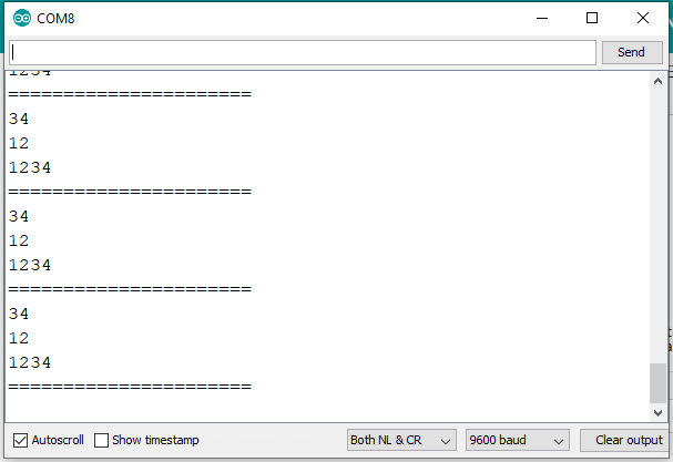
Serial.print(x, HEX); //show the value of x onto Serial Monitor
flag = false; //reset the flag
}
}
ISR(SPI_STC_vect) //MCU/Slave comes into this ISR routine when a data byte arrives to Slave
{
x = SPDR; //bring data from SPDR Register into variable x
flag = true; //set flag to tell loop() function that variaable x contains data that come from Master
}
...see next post.
Ch-7OnlineLec.pdf (291 KB)