8.1 Introduction
(1) Interrupting the MCU means telling it to suspend what it has been doing. For example: In Fig-8.1, the MCU is continuously blinking L (built-in LED of UNO) at 1-sec interval. "Blinking L" is a job that is known as "Main Line Program (MLP)".

Figure-8.1: Demonstration of the interrupt process of ATmega328P MCU
(2) Now, ask the MCU by pushing the external switch K1 to suspend the MLP of Step-1 and then blink LED1 (Fig-8.1) only for 3 times at 2-sec interval and then resume the MLP. "Blinking LED1" is a "side job" which is known as "Interrupt Sub Service Routine (ISR)". The symbolic name of the ISR in Fig-8.1 is: ISRINT0 (ISR due to interrupt at INT0-pin). Practically, the ISR routine should be as short as possible. Why should the ISR routine be short?
(3) The "external switch K1" is called an "Interrupting Device".
(4) When K1 is pressed down, the signal level of INT0-pin (Fig-1) of the MCU changes from HIGH to LOW; as a result, the MCU gets interrupted. The signal at the INT0-pin, which interrupts the MCU is called "Interrupting Signal". The symbolic name of the interrupting signal in Fig-8.1 is: IRQ0 (interrupt request 0). The HIGH level at DPin-2 (Fig-8.1) comes from 5V rail via "internal pull-up resistor Rip".
(5) The value of the interrupting signal is also known as "Trigger Level". The options for trigger level are (Fig-8.2):
(a) FALLING (falling edge FE),
(b) LOW (active low AL), and
(c) RISING (rising edge RE).
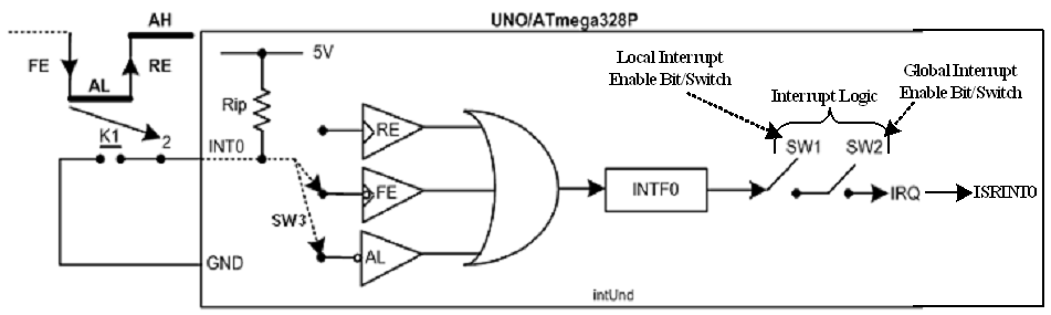
Figure-8.2: Interrupt trigger levels of ATmega328P MCU
Note: (a) At the presence of any event (LWO or FE or RE) at DPin-2, the INTF0 bit/flag of the MCU assumes HIGH state. This flag generates interrupt signal (IRQ) for the MCU provided SW1 (called local interrupt enable bit for INT0 interrupt) and SW2 (called global interrupt enable bit for all interrupts, Fig-8.8) are put into closed conditions (enabled states) in the setup() function. SW1 and SW2 together makes "something" what is called the "interrupt logic". More information on INTF0 flag could be found in Section-8.2 and datasheets.
(b) SW1 and SW2 becomes closed means "interrupt logic" becomes enabled when this code: attachInterrupt(arg1, arg2, arg3); is executed in the setup() function.
(6) In Fig-8.1, we observe that the ATmega328P of the UNO Board has two physical pins (Pin-4, 5) to receive interrupt signals from external sources. The symbolic names of these two pins ate: INT0 and INT1 which are connected with DPin-2 and 3 respectively.
(7) After interruption, the MCU will suspend the MLP and then will jump to ISR routine; therefore, a code should be executed in the setup() function to establish a relation/connection between DPin-2 (IRQ0 comes to INT0-pin of MCU via this DPin-2) and ISRINT0 routine. The following is the code that makes the said relation/connection.
attachInterrupt(digitalPinToInterrupt(DPin), ISRName, TriggerLevel);
==> attachInterrupt(digitalPinToInterrupt(2), ISRINT0, LOW); //for INT0 interrupt
Note: The above code also enables "interrupt logic (Fig-8.2)" so that the MCU is interrupted at the arrival of an interrupt signal. The "interrupt logic" is composed of:
(a) "Local Interrupt Enable Bit" represented by SW1 in Fig-8.2. It must be in closed position so that the MCU can be interrupted by an interrupt signal.
(c) "Global Interrupt Enable Bit" represented by SW2 in Fig-8.2, It must be in closed position so that the MCU can be interrupted by an interrupt signal.
(8) Let us note down that the MCU deactivates/disables "global interrupt enable bit" (means opens SW2 of Fig-8.2) before going to ISR routine so that it is not further interrupted until the current side job (the ISR routine) is completed. Also note that the delay() function needs active state of "global interrupt enable bit" for its own functioning. Therefore, it will not be possible to execute delay() function in the ISR routine. Now, the blinking job of LED1 of the ISRINT0 routine has to be done in the loop() function as "global interrupt enable bit" remains enabled in the loop() function. How will loop() function know that there happened an interrupt event? This will be known to the loop() function by setting up a flag into true state in the ISR routine. The loop() function will test the flag and if found true, it will understand that interrupt had happened and then it will blink LED1 for 3 times at 2-sec interval using delay() function. For the codes, please see Section-9(f).
(৮) ধরুন, আমার সাথে একজন ছাএ কথা বলতেছে। এই ছাএের সাথে আলাপ শেষ না হওয়া পর্যন্ত, আমি ২য় কোনো ছাএের সংগে আলাপ শুরু করবোনা; অর্থাৎ, ২য় ছাএের কাছ থেকে আসা ইনটারাপট (interrupt) আমার দ্বারা অগ্রাহ্য হবে। মাইক্রোকন্ট্রোলালের (MCU) ক্ষেএেও একই রকম ঘটনা ঘটে। মাইক্রোকন্ট্রোলার, ISR routine-এ প্রবেশ করার আগ মূহু্র্তে, "Interrupt Logic"-কে নিষ্ক্রিয় (disable) করে ফেলে। ISR routine-এ গিয়ে LED1 ৩-বার ২-সেকেন্ড পর পর বিলিংক (blink) করার কথা এবং এ কাজের জন্য delay() ফাংশন ব্যাবহার করবে। কিন্তু, এই delay() ফাংশন কাজ করবে যদি "Interrupt Logic" সক্রিয় (enabled) থাকে। "Interrupt Logic" অলরেডি নিষ্ক্রিয় করা আছে; অতএব, ISR routine-এ LED1-কে বিলিংক করা যাবেনা। বিলিংকিং কাজটা loop() ফাংশনে নিষ্পন্ন করতে হবে; যেহেতু, loop() ফাংশনে "Interrupt Logic" সক্রিয় থাকে। তা হলে, প্রশ্ন উঠে--loop() ফাংশন জানবে কেমনে যে, ইনটারাপট ঘটনা ঘটেছিল? loop() ফাংশনকে এই জানানটা দেওয়ার জন্য, ISR routine-এ একটা flag সেট করা হয়। মাইক্রোকন্ট্রোলার loop() ফাংশনে এই flag টেষ্ট করে এবং এর মান true পেলে বুঝে নেয় যে ইনটারাপট ঘটনা ঘটেছিল; আর, কেবল মাএ তখনই LED1 ৩-বার ২-সেকেন্ড পর পর বিলিংক করবে। কোডের (code) এর জন্য Step-9(f) দেখুন।
(9) Let us create the sketch to accomplish the interrupt process for INT0 interrupt of Fig-8.1.
(a) Begin with two blank functions -- setup() function and loop() function.
(b) Place the following codes in the setup() function to accomplish the tasks (known as initialization) briefly described in the comment field.
Serial,begin(9600);  //to connect Serial Monitor
pinMode(13, OUTPUT);      //to drive L (built-in LED of UNO
digitalWrite(13, LOW);      //L is initially OFF
//---------------------------------------------------------------
pinMode(8, OUTPUT);      //to drive LED1 of ISRINT0 routine
digitalWrite(8, LOW);      //LED1 is initially OFF

//---------------------------------------------------------------
pinMode(2, INPUT_PULLUP);  //internal pull-up is connected with DPin-2/INT0-pin
attachInterrupt(digitalPinToInterrupt(2), ISRINT0, LOW);//make connection between INT0 and ISRINT0
(c) Place the following codes in the loop() function to blink L continuously at 1-sec interval.
void loop()
{
    digitalWrite(13, HIGH);
    delay(1000);
    digitalWrite(13, LOW);
    delay(1000);
}
(d) Place the following ISRINT0 routine at the end of the loop() function.
void ISRINT0()
{
   flag = true;   //flag will allow to blink LED1 for 3 times at 2-sec interval using delay() function
}
(e) Place the following declarations in the global area of the sketch.
byte counter = 3;    //LED1 of ISRINT0 routine be executed for 3 times via the loop() function.
volatile bool flag = false;
(f) Re-write loop() function as follows so that the LED1 could be blinked in the loop() function at 2-sec interval using delay() function when an interrupt signal arrives at the INT0-pin of the MCU.
void loop()
{
  if (flag == false)    //interrupt has not occurred; keep blinking L
  {
    digitalWrite(13, HIGH);
    delay(1000);
    digitalWrite(13, LOW);
    delay(1000);
  }
  else    //interrupt has arrived at INT0-pin via DPin-2; blink LED1 for 3 times
  {
    do
    {
      //-------------------
      digitalWrite(8, HIGH);
      delay(2000);
      digitalWrite(8, LOW);
      delay(2000);
      //-------------------
      counter--;
    }
    while (counter != 0);
    flag = false;
    counter = 3;
  }
}
...see next post.
Ch-8OnlineLec.pdf (467 KB)


