I can provide you with a picture diagram like you show in post #1
Let me know.
@soundproofskin
There seem to be two interpretations of what you are looking for:
- a circuit that takes as an input any waveforms like these
and converts them to waveforms like these
which would require an op amp and dual power supplies.
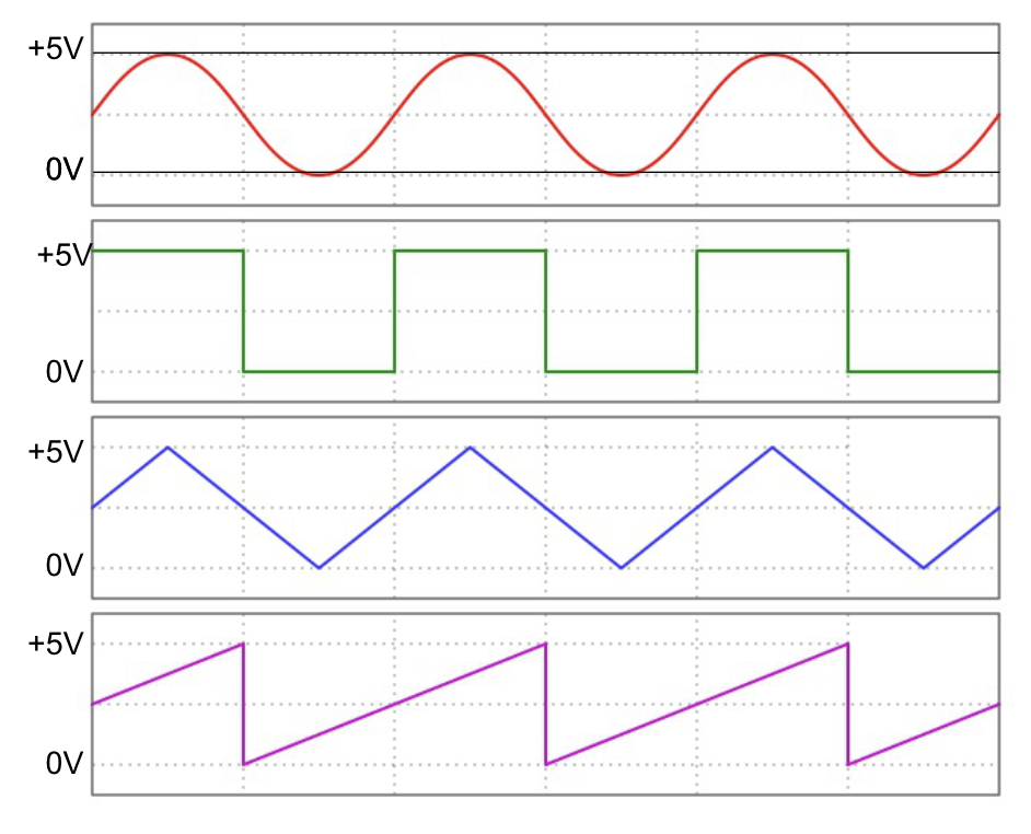

or 2) something that just operates on a simple on/off signal like the green waveform and shifts its level to +/- 5V.
Can you say which?
1 Like
This is a bit tricky for me to answer because those waveforms to me are the shapes one would get out out an oscillator for musical application, but I know that the Arduino has a PWM so there are non-musical applications, and I'm probably going to confuse things here.
In Pure Data, the software I'll be using on my laptop, I will be able to for example:
- send a fixed 'on' signal of a specific voltage that could tune an oscillator to a specified pitch for a drone
- automate the above signal to modulate around the specific voltage by a fraction of a voltage to detune the pitch very slightly to add a bit of warble character movement
- create on/off pulses like a square wave to function as a metronome
- automate a slider to move from -5v through 0v to +5v and back in a loop over a specified time (creating a sort of low frequency oscillator)
- assign voltages to the keys of a midi keyboard controller, sending a specified voltage for each key I play
Technically I'm not sending voltages from the software of course, I'm sending numbers through the serial port to Arduino, which then sends them to the DACs, but in the software I can program a patch so that everything works in a -5 to +5 range so I'm thinking in voltage.
So, from my very uneducated perspective it sounds like your second interpretation, in that I will send intentionally chosen specific voltages, within the +/- 5V range, from Arduino to my synth. Except that it is not a simple on/off signal, it can go up and down like and LFO, or jump around eccentrically within that voltage range.
The synth reads the voltage and what it does with it depends on the function of the synth module, e.g. turns on an actual saw wave oscillator that I can sequence.
I hope that makes sense, I'm learning on this forum that I'm quite bad at explaining myself!
I think from your explanation that the opamp with dual polarity power supplies is the solution then.
From my experience with low noise analog signal processing (which for music applications is probably what you are looking for) it is crucial to use power supplies that are as low noise as possible. DC/DC converters will have a high frequency noise component that is difficult to filter but may not be audible in your application. Purely analog power supplies can have 50/60 Hz noise but it's pretty easy to filter out. Intelligent ground connects are important as you probably already know.
Stealing the power from the rack connectors would probably be the best approach since it is no doubt pretty clean. You could prototype with a couple of 9V batteries if you need to.
MAX232 is not analog, apart from the supply part. So it would be 1 or 8 MAX232’s plus 8 opamps (possibly 3 x 8 opamps).
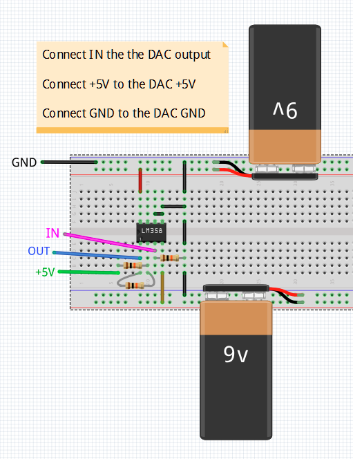
Since you are new to all of this, I suggest you experiment with this circuit. It uses a very common and inexpensive LM358 op-amp and two 9V batteries. After you have tried it, you can move on to a +/- supply.
2 Likes
No.
That is just being silly, and basically shows you don't know what you are doing.
No. This is a standard technique used with analogue synths. They use a DC voltage to feed into the synth at a conversion rate of one volt per octave. These voltages can range over minus five volts to plus five volts. If you feed higher than five volts it just hits the rail of the control so no harm done. The same Is true for voltages lower than minus five volts.
The big problem here is people, with the best will in the world, who know nothing about analogue synth control. Hence some odd ball suggestions.
@soundproofskin
This is the schematic diagram for the picture diagram in Post #46 for when you get to the point where you want to modify or add to the circuit or just figure out how it works.

Update: Add 5V precision reference for 5V.
@jim-p
Maybe I shouldn’t wake the bear, but: OP works from his laptop. The circuit is indeed simple. But: the output is referenced to the +5V, which comes from USB. When the USB voltage drops from 5.25V to 4.75V what happens to the opamp output? (The DAC isn’t bothered, internal reference, output referenced to GND.)
Could add a 5V shunt reference to the circuit.
This 5V reference needs to be powered from the battery, not from USB (that might be 4.75V).
@soundproofskin
That is not a schematic of what I provided.
If you have questions, please let me know.
It not expensive at all and using an RS232 driver/reciever makes absolutely no sense at all.
You won't find a simpler or cheaper solution than what I have proposed.
2 Likes
As usual Jim you are jumping at things you don't understand. Give it a rest won't you please.
Big words, let see your solution
Read the thread won't you please, I have explained the problem and proposed a solution, as have a few other in the replies before me.
I don't see it. Which post # ?
I do see you telling @soundproofskin that they don't know what they are doing but nothing useful or constructive.
1 Like
Thank you @jim-p for the breadboard illustration, that's really clear for me as a beginner. Thanks @EmilyJane for the schematic also. Thanks everyone else who has chipped-in so far too. I'm going to order LM358 and the other bits I need to have a go at making that, and pick apart the circuit to to learn about what is going on.
If I can get that working I'll then see about how to power it via a ribbon cable from my rack.
@Grumpy_Mike I've tried to make very clear that I am a complete beginner. It's frankly a miracle that I have got the project to where it is so far, I hadn't touched a breadboard in my life before starting this project, never heard of a DAC or a multiplexer, and never heard of Arduino, let alone opened the IDE and started tweaking code. You have no obligation to help me, same as anyone, but you did come into this thread and decide to contribute something so I'm going to assume that under your grumpy persona your intention is good and that you want to help. Stating the name of a product (MAX232) as a solution I guess is a valid response to someone who knows what they are doing and just needs a push in the right direction, but for someone just starting out it is impossible to grasp. Do you have more details on how one would use it? An illustration/schematic if it is not asking too much.
Ok Jim let me talk you through it.
The use of a single RS232 allows you to generate a split supply. To be fair so does yours, but at a much higher cost. Understand that?
However the thing that you don't seem to understand is that your "solution" using Op amps will simply not work. The resistor values are fixed, where as CV voltage controlled synths require these values to be variable so they can be adjusted from the controls.
My solution to this would be to take the split supply provided by the MAX232 and control the voltage it outputs using a digital pot. Of course you would have to choose one that could operate outside the normal 5V range, but there are types available.
The circuit would require one digital pot per CV output, and you can have as many as you like. This way you can limit the output to what ever value you want.