Hello Simple think
I tried this int LDR_Sensor=analogRead(CYD_LDR_GPIO34);
I don't have a 3V3 on the LDR. Any clue
Hello Simple think
I tried this int LDR_Sensor=analogRead(CYD_LDR_GPIO34);
I don't have a 3V3 on the LDR. Any clue
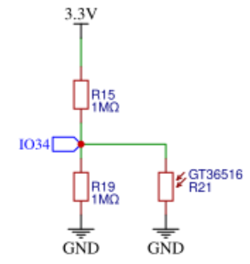
I don't know whether this schematic can be trusted:
int LDR_Sensor=analogRead(CYD_LDR_GPIO34);
I think this thread has been split somewhere. What / where is the question ?
Thx Dave_Lowther I saw this but I don't get
3V3 / 2 The Voltage is Zero V.
Oh, sorry my fault. I get 100 if the LDR is dark. pitch black. Anyway Thx
I've had the same experience with the Cheap Yellow Display (CYD) LDR used as an ambient light sensor. On the specific board I have, the LDR is mounted in full view of the backlight of the TFT display. This has the effect that reading the value of GPIO34 always yields a value of 0. Smothering the LDR sensor with black foam allows the value to rise slightly above zero. I will simply have to find a more elegant way of shielding the LDR.
Another approach would be to switch the back light off at intervals, take an ambient light measurement, then switch the backlight on again. This would, however, be a desperate measure.
Blue arrow points to LDR
Yellow arrow indicates beam from backlight.
That's a fantastic diagnosis, and that picture makes it super clear why the LDR sensor is basically useless out of the box!
What a design flaw to have it sitting right in the backlight's beam. Shielding it seems like the most practical solution if you can't live with the turn-off-and-measure approach.
I've never used an LDR on CYD, but here's a fix to improve the detection range:
Thanks for that. hexeguitar (your link) has certainly looked at the whole CYD thing in a lot of detail. At some point, though, you just design your own board instead of heavily modifying an existing design.
I'll wait until it is dark here before I check if the range is sufficient. I'll need only 2 or 3 light levels with some hysteresis to prevent flicker. The CYD I have (ST7789 based) has a very efficient backlight with a significantly lower current consumption some of the plain ILI9341 screens I have but I still need the backlight control to prevent the device lighting up the whole room at night.
I referred to that page as a guide to adjusting the gain of amplifier to fix severely distorted speaker output.
I haven't actually powered it yet, but I bought a "Not So Cheap Black Display" with an ESP32-S3 installed ![]()
I've now played about with the LDR for the purpose of controlling the screen brightness of the CYD according to the ambient light level. I have settled on two levels, one for daylight conditions and one for night time. Basically, I do not want the room strongly lit at night from the display but the display must, of course, be readable at all times.
Modifications to the CYD.
To help ensure that the LDR is not directly illuminated by the backlight shining through the display edge I have used a sliver of insulating tape to isolate the two components.
The LDR resistor network on the CYD is not very practical for normal usage and appears to see only full brightness unless it is ultra dark so I have made two changes. (1) removed R19 and (2) replaced R15 with a 47K resistor which I found on an old circuit board. Beware. This is not easy. I used a hot air station. My current belief is that this circuit was originally designed for an ESP8266 where the voltage tolerated by the (only) analog pin was 1v.
Globals:
const int LEDPIN = 21;      // backlight
const int LDRPIN = 34;      // LDR
const int frequency = 500;  // PWM Frequency in Hz   fails if < 200
const int resolution = 8;   // Resolution in bits (from 1 to 15)

// display backlight brightness PWM. Code compatible with ESP32 Arduino 3.x core
const uint8_t HIGHBRIGHT = 220;  // duty cycle 8 bit, max 255 (full on) Use max unless display gets too hot.
const uint8_t LOWBRIGHT = 31;    // duty cycle 8 bit, min 0 (full off)
// ensure a dead band between the level triggers below (hysteresis) to avoid thrashing
// A wide band is necessary if there is light leakage from backlight to LDR
// Values dependent on preferences and LDR resistors. Here R15=47K and R19 removed.
const uint16_t HIGHBRIGHT_TRIGGER = 300;  // 12 bit Analog value (inverted)
const uint16_t LOWBRIGHT_TRIGGER = 500;   // 12 bit Analog value (inverted)

uint8_t ledBrightCur = HIGHBRIGHT;
Setup():
  ledcAttach(LEDPIN, frequency, resolution);
  ledcWrite(LEDPIN, ledBrightCur);
Loop():
  static uint32_t lastAmbLtCheckAtMs = 0;
  if (millis() - lastAmbLtCheckAtMs > 1000) {
    lastAmbLtCheckAtMs = millis();
    int ambLightLevel = analogRead(LDRPIN);  // 12bit, higher analog value = lower ambient light
    Serial.printf("AR = %d \n ", ambLightLevel);
    // compare ambient light against trigger levels with hysteresis
    if (ledBrightCur == HIGHBRIGHT && ambLightLevel > LOWBRIGHT_TRIGGER) ledBrightCur = LOWBRIGHT;
    else if (ledBrightCur == LOWBRIGHT && ambLightLevel < HIGHBRIGHT_TRIGGER) ledBrightCur = HIGHBRIGHT;
    ledcWrite(LEDPIN, ledBrightCur);  // 8 bit resolution
  }
Great job, @6v6gt!
I've bookmarked your post. I'm sure it will be useful to someone.
I don't feel the need for an LDR at the moment, but I bought more 0603 resistors than I could ever use in my lifetime ![]() to adjust the gain of the SC8002B amplifier on a CYD, so I'd like to try one out if I get the chance
to adjust the gain of the SC8002B amplifier on a CYD, so I'd like to try one out if I get the chance ![]()