I am a beginner and like to produce my first PCB for controlling a two PSUs and Fans. So perhaps you can check of there are some best practices I did not know or other faults/comments that should be changed before producing a PCB.
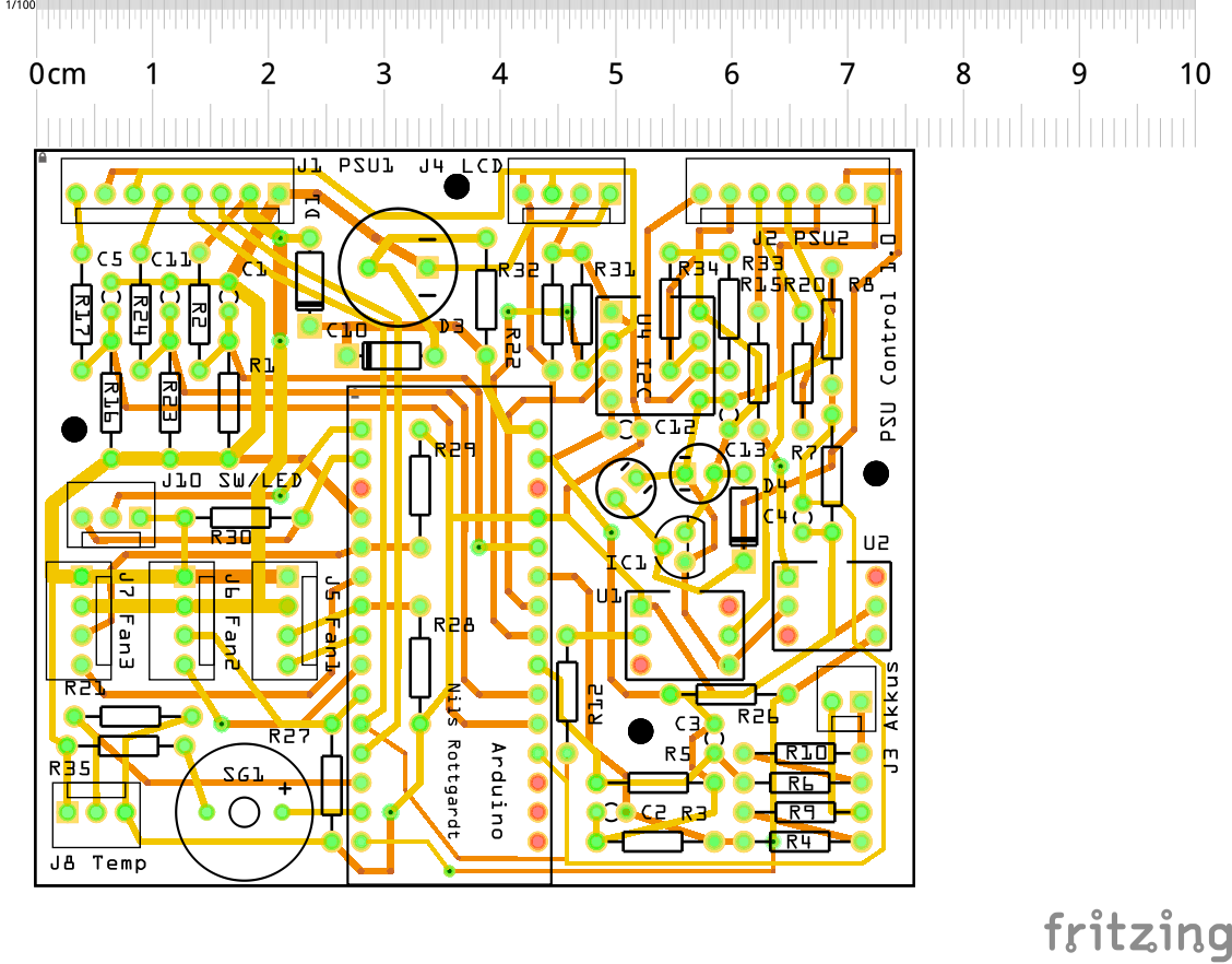
I miss power/ground planes, and you really have to do something about the silkscreen or you have no idea which part an annotation belongs to - if it's readable at all, and not on top of another annotation or under a neighbouring part.
All traces are the same width; this may or may not be an issue depending on the currents flowing through them.
90° angles are usually avoided to limit signal reflections. Usually this becomes only an issue for signals at the high end of what an Arduino can handle (>1 MHz), probably not an issue for you.
Ground/Power is delivered by PSU1 and there is no additional source.
There is no large current in my oppinion, perhaps you can comment it. There are 5 consumers: 3x fan, 1 LED and 1 buzzer. Should I resize one of this?
Only I2C, Buzzer and PWM for fans have higher rates. Created it with 90° angels because I thought this is the best, good to know. Should I change this as it should not larger than 400Khz?
When building PCBs with KiCAD I even have to put a lot of effort in even making 90° corners... it won't do that by itself when drawing traces unless it has to... And who am I to overrule the design rules made by people that know a lot more about building PCBs?
I see a very high risk of an overheating regulator of that nano in your near future. Use a 12V-5V buck converter instead, connected to the 5V pin.
Also I have to say Fritzing continues to impress me. It's really doing a great job in making schematics messy and hard to read, breaking all kinds of conventions (that Nano is kinda upside-down: GND on the top, +V on the bottom, that regulator is sitting on its side). Also most of your polarised caps don't have a value.
16V is a quite low rating for C10. I'd use 25 or 35V (or higher) for that one. Costs barely any more, and is much safer.
To measure the absolute value of your 12V and 24V supplies, you better use a voltage divider to bring the voltage down to about 1V and read using the internal 1.1V reference (remember to calibrate it; it has a 10% tolerance but is much more stable than the default reference which is Vcc).
I am using the Arduino Every and the regulator is rated up to 200mA for supporting other components. I tested it and the overall current is about 100mA if the buzzer is making noice. So it should be fine in my oppinion or what did you thing?
I using the 4.3V interal reference of the every which has the same ratings like the 1.1V reference to avoid larger resistors. As it has the same behavior it should be fine in my oppion.
I tried other tools in the beginning but for a dummy fritzing is much easier to understand. But yes, the schematics driving me crazy at the end. But it was a quite of fun developing it.
100 mA * (12V - 5V) = 700 mW. Or I would have thought so. I haven't heard of the Nano Every yet but that makes a world of difference: according to the schematic it uses a buck converter in IC form, the MPM3610, instead of a linear regulator. I didn't know such things even exist! Just the thing quite a few of my boars can benefit from, instead of soldering a buck converter module on top, looks so much better. That's one of reasons I'm on this forum, so many new things to learn.
The schematic shows that it uses an MPM3610 IC for Vin (up to 21V according to the datasheet), which can supply up to 1.2A. That's pretty impressive, and the stated efficiencies especially at higher currents are really good. So indeed, you'll be fine with this.
That said, in your schematic is also a 7805 regulator. Not sure what that is supposed to do, but chances are you can rely on the buck converter of your Nano Every.
And the Every is also cheaper. I like it but also burned one because of my fault...but thats life.
The 7805 is for supporting a second ground which is decoupled via opticouplers (control lines and I2C).
I have to connect 2 PSUs having diffrent grounds so thats the case I have to use 2 voltage regulators (MPM3610 and 7805).
What do you thing about the PCB. Thats more or less my actual topic as I build everything on the breadboard and never build a PCB?
NILSRO:
And the Every is also cheaper. I like it but also burned one because of my fault...but thats life.
Really? I saw that MPM3610 chip on Digikey for about USD 1.8 per piece in volume. That's about what I pay for a complete Nano.
What do you thing about the PCB. Thats more or less my actual topic as I build everything on the breadboard and never build a PCB?
See #2 for most concerns.
Make sure R28 and R29 fit under your Nano.
Then your 78xx. Took me a while to find it on your board as I was looking for a TO-220 footprint... Are you sure that shouldn't be a 78L05? That one comes in TO-92, the 7805 is normally TO-220. That also limits the current even further as a TO-92 (that's what you have drawn on that PCB) can handle no more than 500mA, that's about 80 mA of current for 12V to 5V regulation.
My general practice is to add Ground planes on the top and bottom layers, with vias interconnecting them where possible, and ditch the Gnd traces all over the board. Can help with cooling, can help with emitted RF noise, can help with power supply decoupling (the two planes can act like a big capacitor).